sorry, can you please try to explain your question a little more?
Sorry to bother you.
I think
yaw_vec_correction_quat = thrust_vec_correction_quat.inverse() *att_from_quat.inverse()*att_to_quat;
Is it a bit of a problem
it should be
yaw_vec_correction_quat = thrust_vec_correction_quat * att_from_quat.inverse() * att_to_quat;
because
thrust_vec_correction_quat is a rotated Qcb_>tb1 in inertial frame (cb is current body frame ,tb1 is the target body frame but only have tilt)
if use
yaw_vec_correction_quat = thrust_vec_correction_quat *att_from_quat.inverse()*att_to_quat;
get
Qtb1->cb * Qn->cb * Qtb->n = Qtb1->cb * Qtb->cb (n is the inertial frame)
is not the yaw angle
ues
yaw_vec_correction_quat = thrust_vec_correction_quat * att_from_quat.inverse() * att_to_quat;
we can get
Qcb->tb1 * Qn->cb * Qtb->n = Qtb->tb1 (n is the inertial frame)
is the yaw angle
I don’t understand your question clearly. What is “tb1 is the target body frame but only have tilt”. I think originally, the thrust_vec_correction_quat is a rotation in inertial frame, after a rotation it should be a rotation in vehicle frame. So with the original definition, the yaw_vec_correction_quat is a rotation from target frame to vehicle frame.
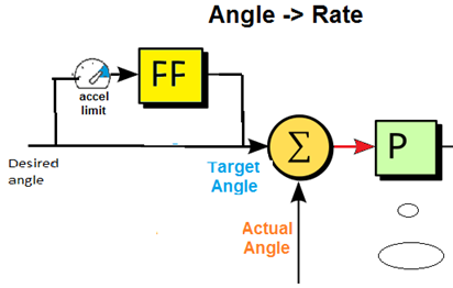
I think the diagram on the document is misleading http://ardupilot.org/dev/docs/apmcopter-programming-attitude-control-2.html I spent much time on the diagram, trying to find the similarity in code structure. But in the end, I found out that it does not reflect the code structure. According to the diagram, the FF branch passes the P(or sqrt)-controller and goes directly to the next stage controller. But in fact FF branch only calculates target angle from the current angle based on acceleration and angular velocity limitations, and then goes to P-controller. So I think the diagram should be changed like in the next diagram
I am curious as to what your backgrounds are and what motivates you to take such an interest in this part of the code?
As I told you before, my background is BOS in programing, and meantime I got a MOE degree in Telecom, so I can understand hardware things too. Before I found it easy to understand the attitude control with Euler angles. But when it is moved to quaternion, it is much harder to understand. This motivates me to take interest in this part of code, and also I can learn much from understanding the code.
So are you doing this as a hobby or is it work for you?
I told you that now I’m maintaining a big quadcopter running Arducopter, this is my work but mainly this is hobby.
My change is wrong. I misunderstood the diagram. Actually, the FF is not a separate, independent branch. It is only an additional branch to the main flow through P-controller. So the diagram is correct.
Hi Leonadt Hall,
I think now I can understand almost everything and things seem to work well. The only thing I still do not understand is in thrust_heading_rotation_angles() where att_diff_angle.x and att_diff_angle.y depend only on thrust_vec_correction_quat() while att_diff_angle.z depends on yaw_vec_correction_quat(). Can you give me more explanation? Thank you in advance.
Hi Leonadt Hall again,
Can you tell me more about att_diff_angle in thrust_heading_rotation_angle() function, please. Why are its x, y, z coordinates defined that way?
Hi everybody,
Can anyone tell me more about att_diff_angle in thrust_heading_rotation_angle() function in AC_AttitudeControl.cpp, please. Why are its x, y, z coordinates defined that way? Thank you very much.
Hello everyone,
It looks strange that no one ansers to my question in the last 2 weeks. I think the att_diff_angle coordinates have an important role in the first stage P-controller. That’s why I’d like to know the way they are calculated.
Sorry I have been too busy to answer. I will get back to this when I can.
OK, thank you. Now at least I know I need to wait for the answer that is not so urgent anyway.
Hi there,
Wanted a little basic help in understanding the attitude controller.
From the code below from the input_euler_angle_roll_pitch_euler_rate_yaw :
if (_rate_bf_ff_enabled) {
        // translate the roll pitch and yaw acceleration limits to the euler axis
        Vector3f euler_accel = euler_accel_limit(_attitude_target_euler_angle, Vector3f(get_accel_roll_max_radss(), get_accel_pitch_max_radss(), get_accel_yaw_max_radss()));

        // When acceleration limiting and feedforward are enabled, the sqrt controller is used to compute an euler
        // angular velocity that will cause the euler angle to smoothly stop at the input angle with limited deceleration
        // and an exponential decay specified by smoothing_gain at the end.
        _attitude_target_euler_rate.x = input_shaping_angle(wrap_PI(euler_roll_angle - _attitude_target_euler_angle.x), _input_tc, euler_accel.x, _attitude_target_euler_rate.x, _dt);
        _attitude_target_euler_rate.y = input_shaping_angle(wrap_PI(euler_pitch_angle - _attitude_target_euler_angle.y), _input_tc, euler_accel.y, _attitude_target_euler_rate.y, _dt);

        // When yaw acceleration limiting is enabled, the yaw input shaper constrains angular acceleration about the yaw axis, slewing
        // the output rate towards the input rate.
        _attitude_target_euler_rate.z = input_shaping_ang_vel(_attitude_target_euler_rate.z, euler_yaw_rate, euler_accel.z, _dt);

        // Convert euler angle derivative of desired attitude into a body-frame angular velocity vector for feedforward
        euler_rate_to_ang_vel(_attitude_target_euler_angle, _attitude_target_euler_rate, _attitude_target_ang_vel);
        // Limit the angular velocity
        ang_vel_limit(_attitude_target_ang_vel, radians(_ang_vel_roll_max), radians(_ang_vel_pitch_max), radians(_ang_vel_yaw_max));
        // Convert body-frame angular velocity into euler angle derivative of desired attitude
        ang_vel_to_euler_rate(_attitude_target_euler_angle, _attitude_target_ang_vel, _attitude_target_euler_rate);
    } else {
        // When feedforward is not enabled, the target euler angle is input into the target and the feedforward rate is zeroed.
        _attitude_target_euler_angle.x = euler_roll_angle;
        _attitude_target_euler_angle.y = euler_pitch_angle;
        _attitude_target_euler_angle.z += euler_yaw_rate * _dt;
        // Compute quaternion target attitude
        _attitude_target_quat.from_euler(_attitude_target_euler_angle.x, _attitude_target_euler_angle.y, _attitude_target_euler_angle.z);

        // Set rate feedforward requests to zero
        _attitude_target_euler_rate = Vector3f(0.0f, 0.0f, 0.0f);
        _attitude_target_ang_vel = Vector3f(0.0f, 0.0f, 0.0f);
    }
and from attitude_controller_run_quat :
if (_rate_bf_ff_enabled) {
        // rotate target and normalize
        Quaternion attitude_target_update_quat;
        attitude_target_update_quat.from_axis_angle(Vector3f(_attitude_target_ang_vel.x * _dt, _attitude_target_ang_vel.y * _dt, _attitude_target_ang_vel.z * _dt));
        _attitude_target_quat = _attitude_target_quat * attitude_target_update_quat;
        _attitude_target_quat.normalize();
    }

    // ensure Quaternions stay normalized
    _attitude_target_quat.normalize();
It seems like when _rate_bf_ff_enabled is enabled, the _attitude_target_quat does not get updated directly from the angles input into the input function, but rather depends on the feedforward rates integrated over _dt.
However, talking about just (atleast) stabilise mode and when the vehicle is dis-armed, the nav_roll and nav_pitch from NAV_CONTROLLER_OUTPUT mavlink messages which effectively show _attitude_target_euler_angle seems to show desired angles (extreme RC stick input seem to take nav_roll to max angle of 45 deg). With this behaviour, it seems like the target attitude is made equal to the desired attitude, which should not be the case when rate feedforward is enabled.
I have also confirmed in my case that the rate feedforward is enabled.
I am confused. Can somebody help?
@sachman when _rate_bf_ff_enabled is enabled, the target response is shaped to achieve the desired (input) angle in a first order fashion (exponential). That is what the ATC_INPUT_TC parameter is used for. It is the time constant to achieve 63% steady state of the input. So with the default ATC_INPUT_TC of 0.15, then if you made a step input with the RC stick then it would take 0.45 sec to achieve that steady state.
When the _rate_bf_ff_enabled is disabled then the requested input becomes the target. There is no shaping in this case.
In the steady state, they will be the same. The difference would be seen in how they achieve steady state. Hopefully this makes sense.
Regards,
Bill
@bnsgeyer,
Thanks for explaining this.
However, some things are still not clear to me, if I may.
Which of the two case would be a steady state: (say, for roll) euler_roll_angle - _attitude_target_euler_angle.x is (close to) Zero, or when error between _attitude_target_euler_angle.x and _attitude_vehicle_euler_angle.x is (close to) Zero?
Well, if its the former, even if I’m giving stick input (extreme right say, roll 45 deg), the vehicle would be in steady state even then? This is again confusing. (Note: The vehicle is dis-armed.)
PS: Just to again assemble the perspective, I was expecting _attitude_target_euler_angle to be an orientation with target angular vel integrated over time _dt (from this :
attitude_target_update_quat.from_axis_angle(Vector3f(_attitude_target_ang_vel.x * _dt, _attitude_target_ang_vel.y * _dt, _attitude_target_ang_vel.z * _dt));
_attitude_target_quat = _attitude_target_quat * attitude_target_update_quat;
)
For _attitude_target_quat to be 45 deg (say, for roll through stick step input), the angular vel would have to be 18000 deg/sec for the last _dt, which obviously can’t be the case. Hence the confusion.
What am I missing?
On a different note, what would be the very first value of _attitude_target_euler_angle, i.e. for the very first iteration of input_shaping_angle() ?
The target angle has nothing to do with the aircraft current angle. The target angle is where the flight controller thinks the aircraft should be based on the pilots input and the shaping for the target angle. And again the shaping only occurs when the eedtorward enabled parameter is set to enable. Otherwise the target angle is with the pilot requests.
When the shaping is on, the steady state that the target angle is trying to achieve is based on the pilot input. So when you make a sharp input (for example a full right stick input) and hold it there (for the example case hold the stick at the max input), target angle will achieve the steady state pilot input request in a first order fashion. You can try this by setting the ATC_INPUT_TC parameter to 0.5. Then make a very sharp stick input in either pitch or roll and hold it there and then watch the target angle response. You will see that it will take about 1.5 seconds to achieve the requested angle.
I don’t know if this will help, but I wrote a thread on the command model or what I term the shaping in this thread. Here is the link.
Bill,
Thanks for explaining things so clearly. It is much clearer to me now.
This was very helpful.
I will also go through the link you provided.