Thanks for your patience and for discovering how interesting and informative are the logs.
…I think if the car was driven manually forwards and backwards on the straightaway before starting the mission it would be OK…
I had tried that learning possibility before, but in Manual, without any conclusion. I’ll try shortly in Acro and Steering. Anyhow, it is a workaround.
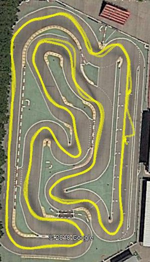
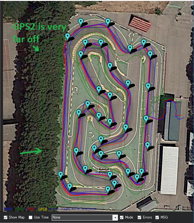
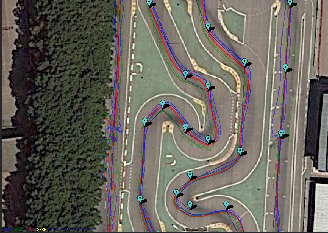
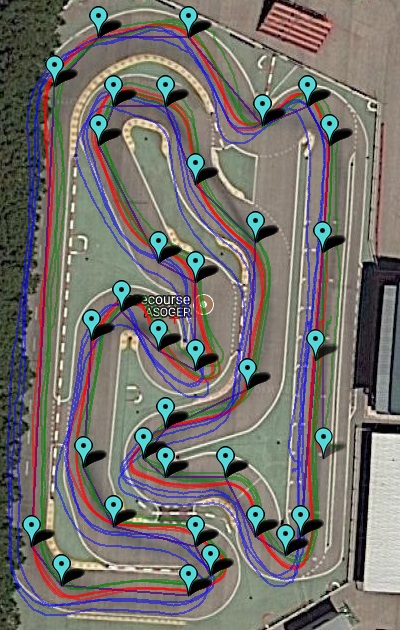
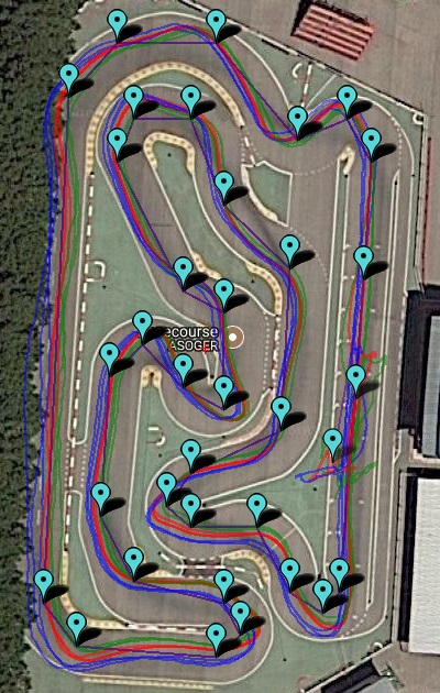
…The position from GPS2 is really very bad…
Well, the car does not go between the trees. I agree that there is something strange with this GPS, so I had changed it, but did not reach a conclusion. I’ll substitute it again and see what happens.
Anyhow, in the logs lat/long/alt don’t differ too much between the two GPS’s.
When I tried one only GPS things didn’t work at all, for whatever the reason.
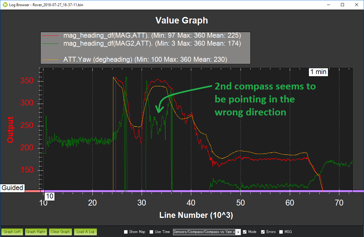
…The 2nd compass appears to be pointing in the wrong direction. I think it’s upside down…
I have never been sure about the definition of the compass positioning. Above I started with one compass at Roll180, which seems what is documented elsewhere.
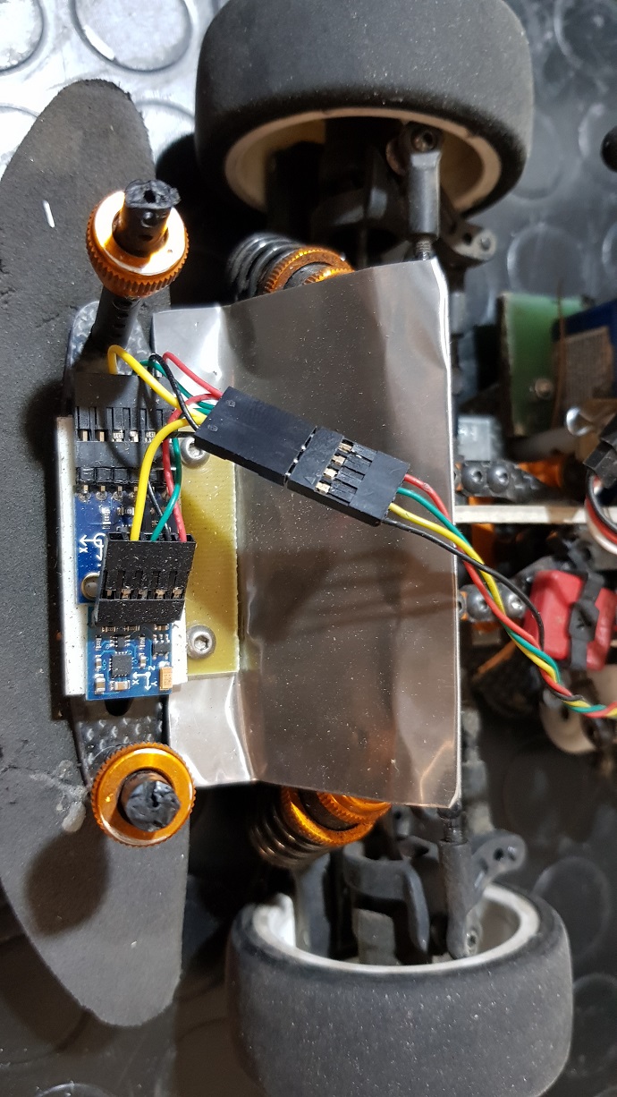
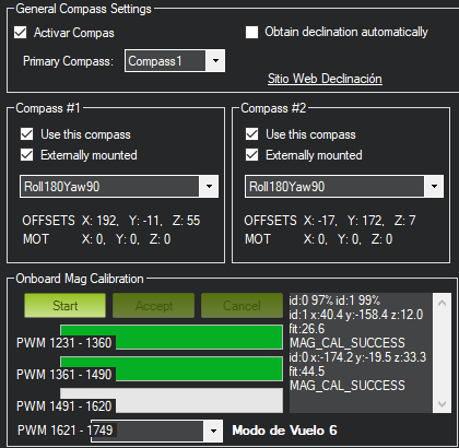
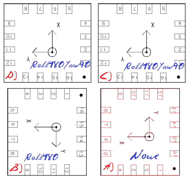
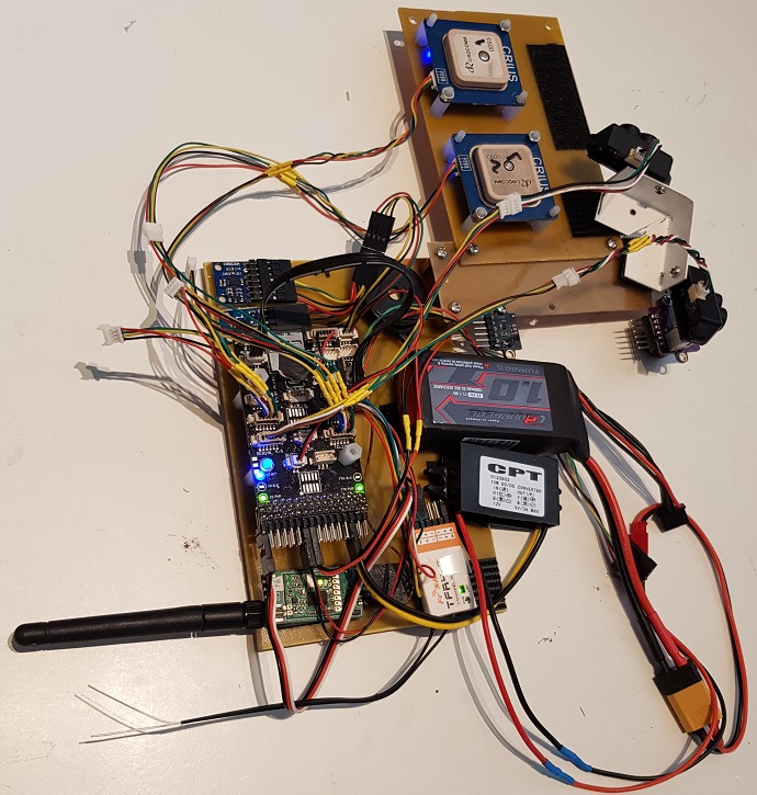
Here is the detail of the actual positioning (HMC5883, QMC5833, Roll180Yaw90) of both external compasses:
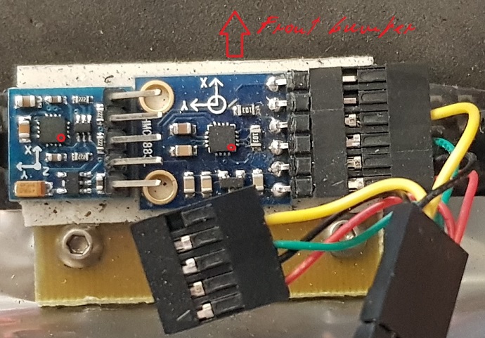
Chip orientation dot is indicated in red. The two near screws are titanium screws. Note that previous orientation above for a single compass was Roll180; rotating it 90º leaves cables more protected.
But note that chip orientation is the same and axes notation in the PCB’s is the same. Although the manufacturers are different, it would be annoying if their rules would be different.
An overall reasoning for compass orientation is deduced from the following figure, obtained from chip’s documentation (compare positioning dots and axes):
A) Internal Pixhawk compass (not used). It is upside down (shown red). It is clear that its orientation is None.
B) First external compass here (Roll180). It is clear that this positioning is obtained rotaing A) 180º, but Roll is not so clear.
C) and D) Actual external compasses, rotating B) 90º.
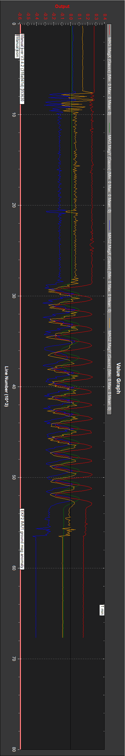
What is really strange is that both compasses, oriented and defined the same, show different behaviour. Although similar in name they are different in software. Can somewhere be a bug?
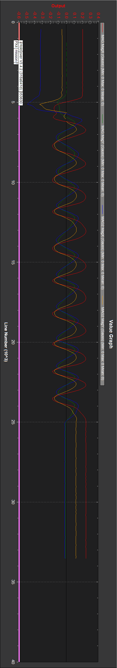
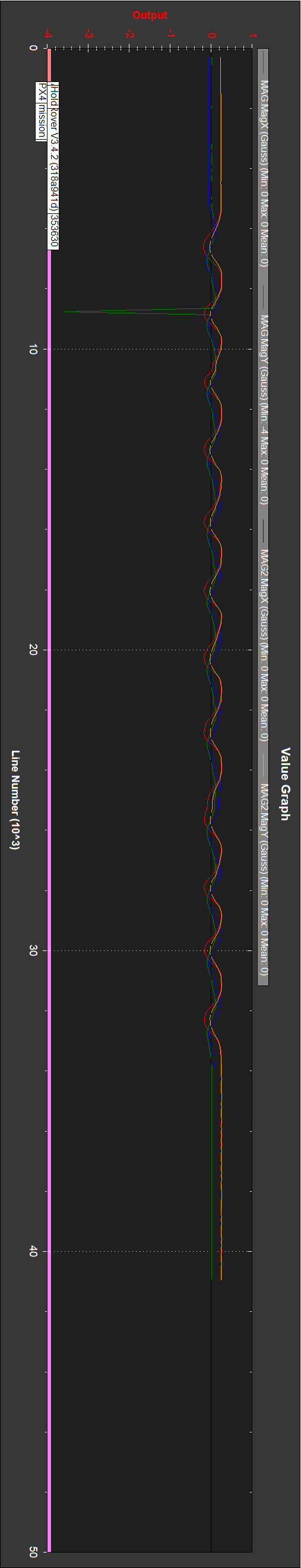
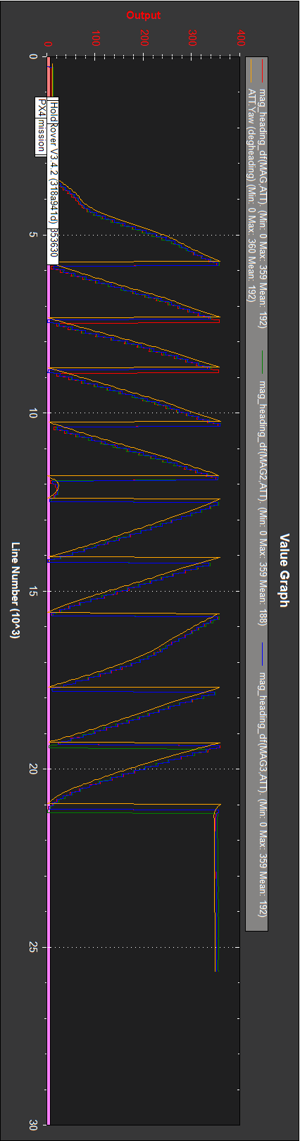
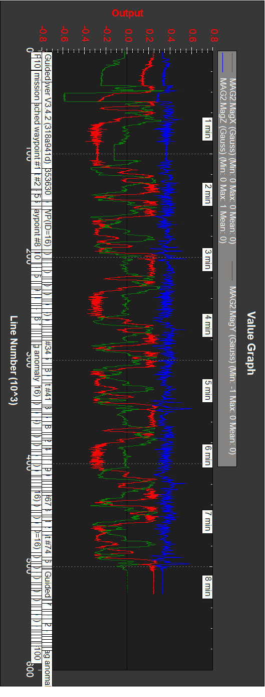
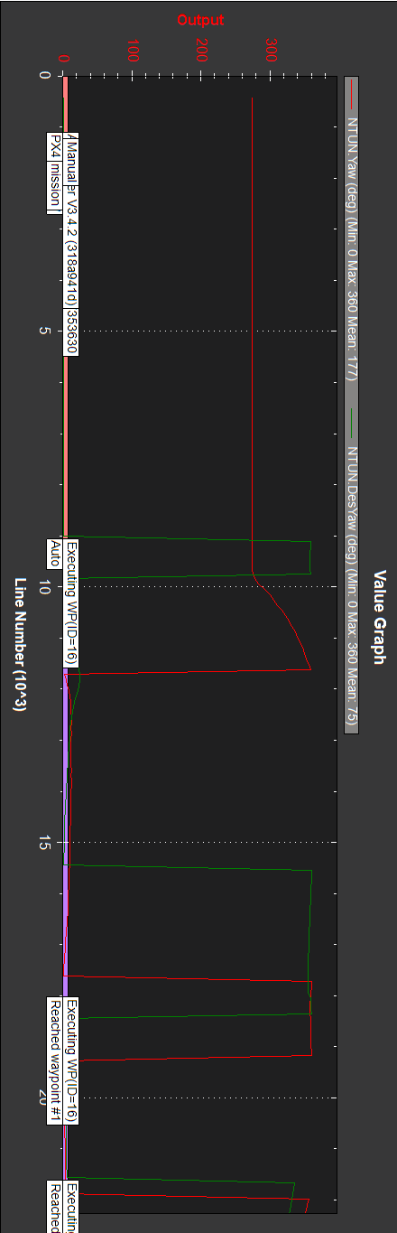
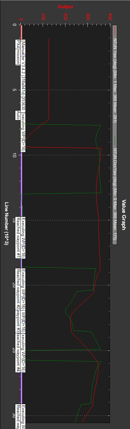
I made at home three logs (v3.4.2), rotating the car uniformly (by hand) over a rotating platform, so yaw is linear and mag is sinusoidal (moreless).
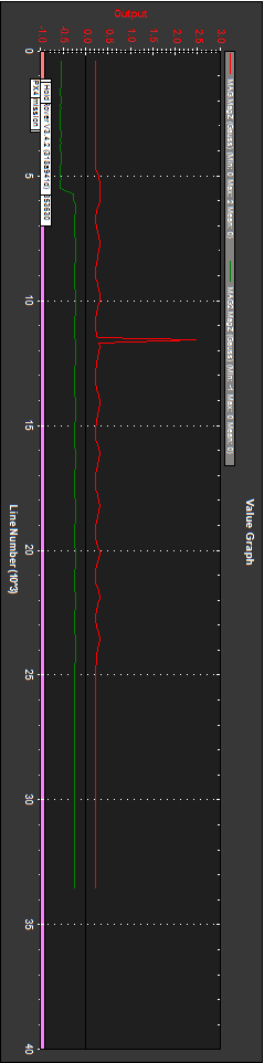
Rover_20180801_192933_motoroff_10cw.bin
Car is rotated 10 times cw.
This the same as you observed.
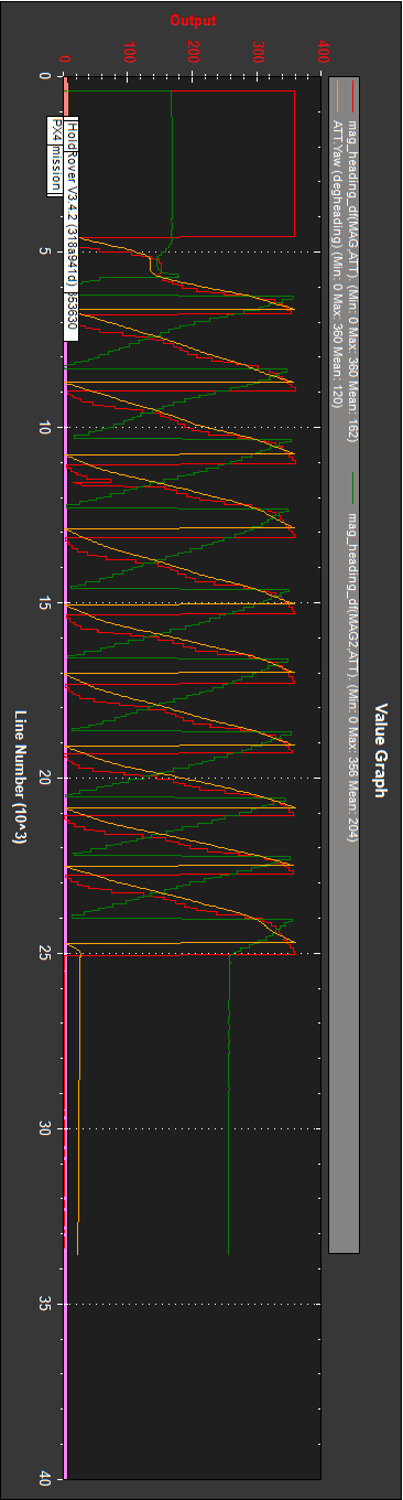
Why is it that the green line for mag_heading_df(MAG2,ATT) has a negative first derivative?
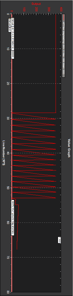
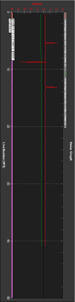
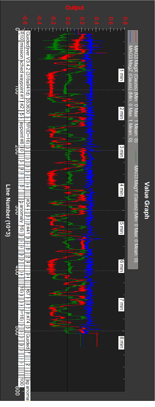
Rover_20180801_193045_motoroff_12ccw.bin
Car is rotated 12 times ccw.
(Spike on compass 1)
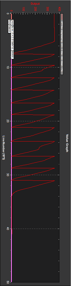
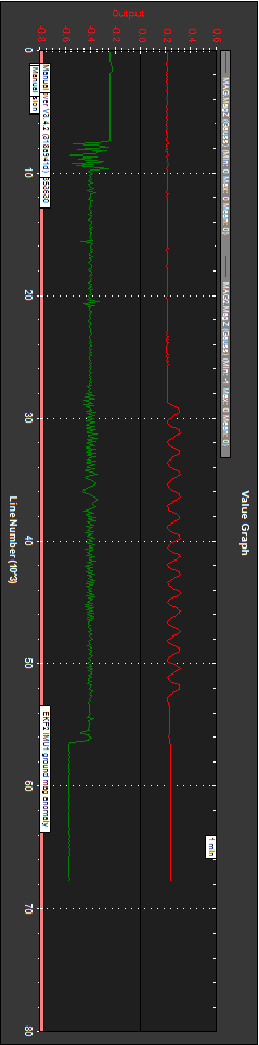
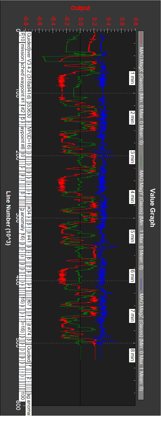
Rover_20180801_193224_motoron_15cw.bin
Car is rotated 15 times cw with motor on (not much difference).
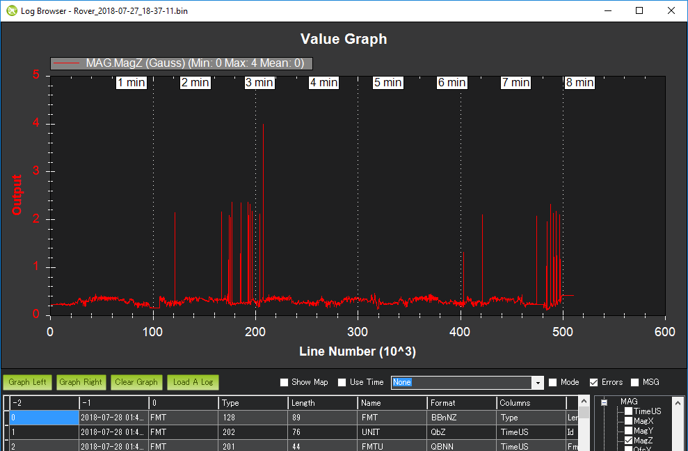
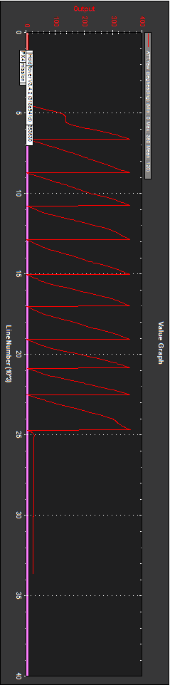
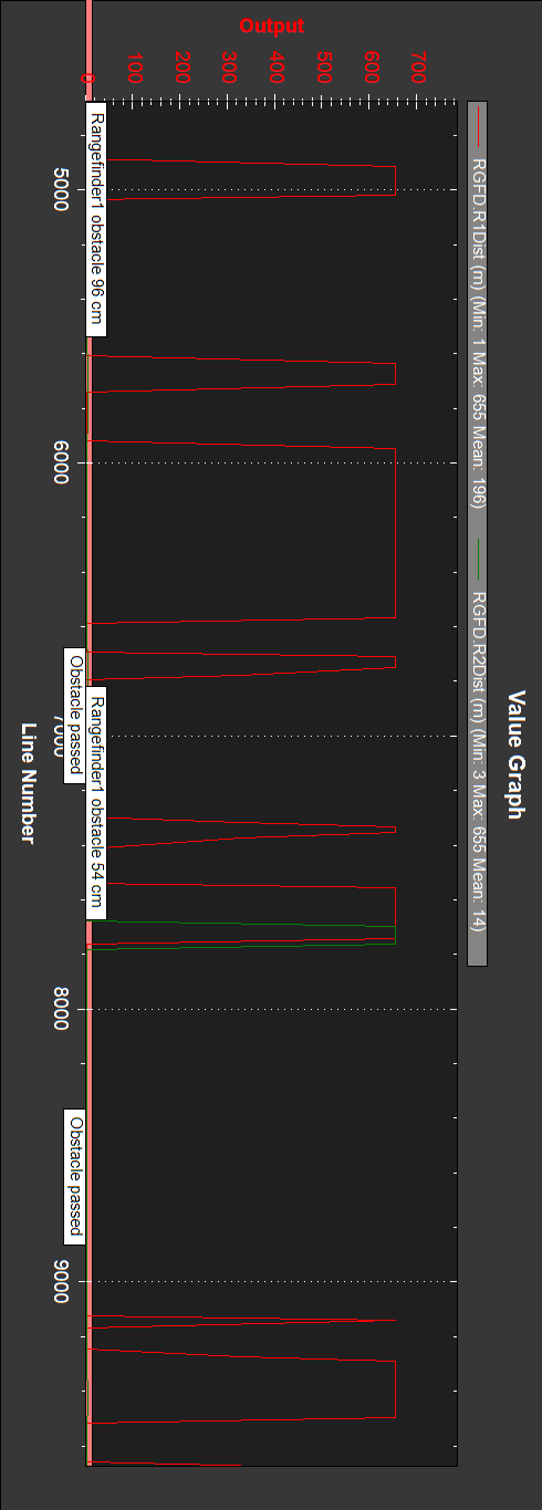
There are some large spikes in the primary compass’s Z axis…
They repeat on above logs on first compass:
10t cw:
12t ccw:
15t cw (motor on):
I’ll change compass 1 (same chip).
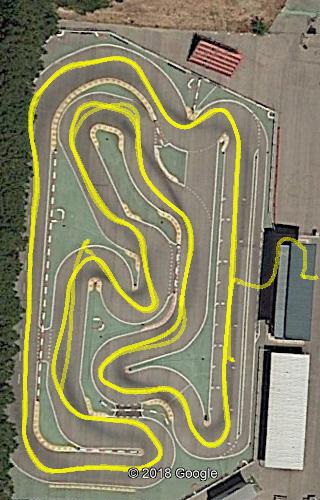
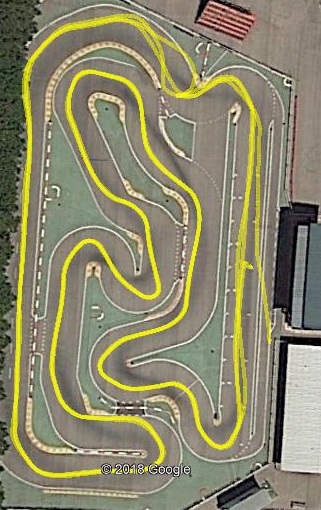
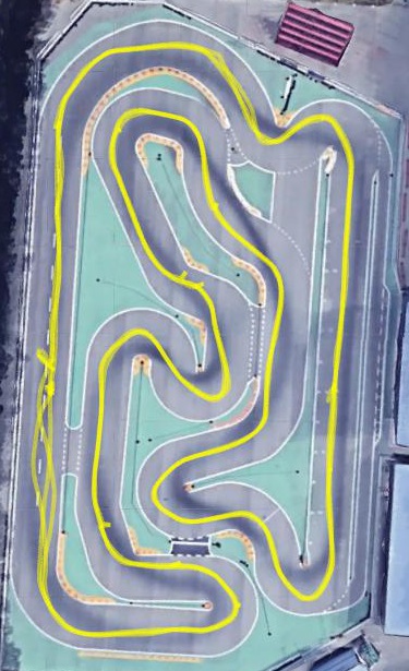
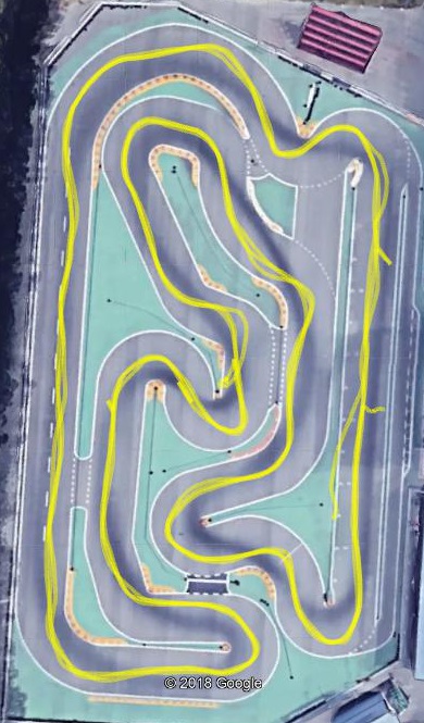
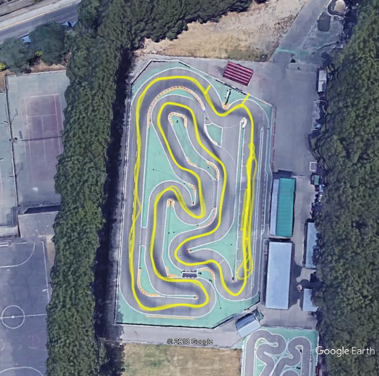
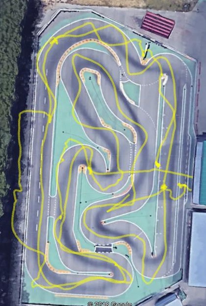
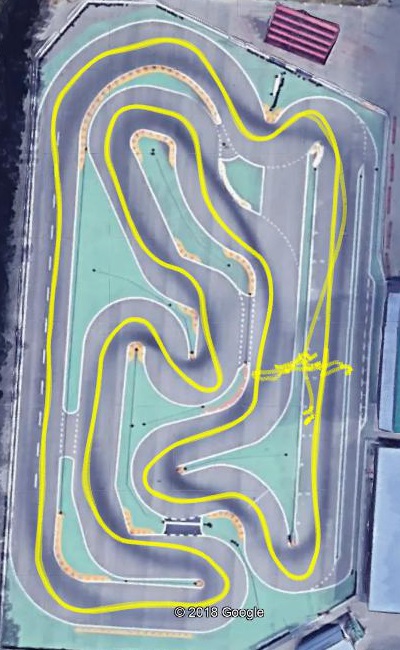
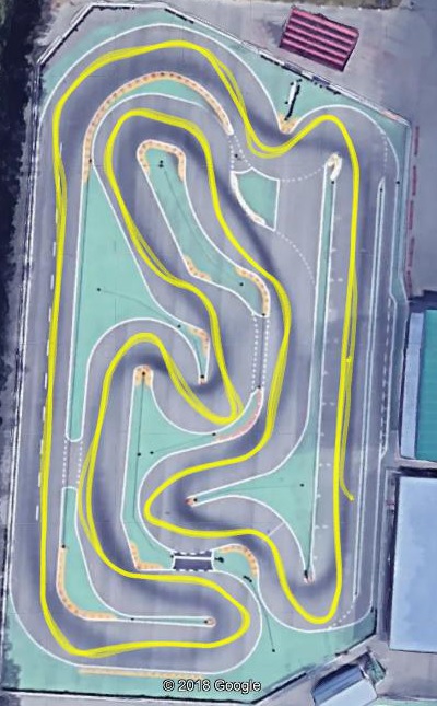
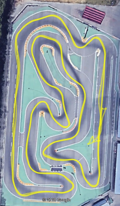
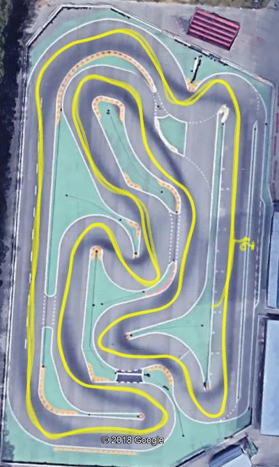
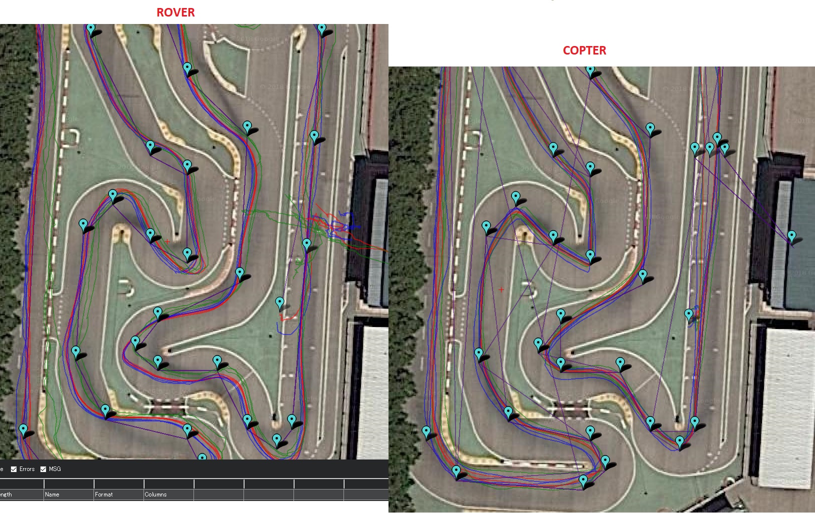
To help you properly I probably need to get a fast Rover of my own and try racing it on a race track here in Japan…
Some on road tracks in Japan:
31°47’26"N 130°44’10"E
31°49’04"N 130°16’41"E
32°43’10"N 130°18’21"E
32°46’04"N 129°48’01"E
33°01’26"N 130°40’02"E
33°01’39"N 131°16’25"E
33°12’17"N 130°18’52"E
33°14’22"N 130°17’17"E
33°17’22"N 130°31’57.50"E
33°19’02"N 130°25’37"E
33°21’46"N 130°24’46"E
33°36’45.50"N 133°34’00.50"E
33°39’41"N 130°49’47"E
33°39’42.50"N 135°54’22"E
34°02’08.50"N 131°55’29.50"E
34°12’22"N 135°23’21"E
34°13’10"N 134°02’48"E
34°17’24"N 135°21’25"E
34°31’36"N 135°39’14"E
34°35’43"N 135°35’57"E
34°37’03.50"N 132°57’25"E
34°37’28"N 136°32’24"E
34°40’17"N 133°57’44"E
34°42’47"N 135°34’59"E
34°45’35"N 135°49’12"E
34°47’11"N 138°02’28"E
34°50’05"N 137°20’27"E
34°50’18"N 136°53’01"E
34°52’47"N 136°59’32.50"E
34°53’06"N 137°26’48"E
34°53’52"N 134°34’43"E
34°58’48"N 138°25’18"E
34°59’33"N 135°37’23"E
35°06’13"N 136°41’18"E
35°08’56"N 136°51’20.50"E
35°09’12"N 135°07’47"E
35°10’06"N 136°30’36"E
35°15’17"N 137°05’59"E
35°17’54"N 136°56’37.50"E
35°19’17"N 136°43’59"E
35°22’28"N 138°34’26"E
35°23’39"N 136°49’08"E
35°24’56"N 136°40’16"E
35°25’23"N 139°21’23"E
35°25’50"N 140°08’04"E
35°29’40"N 140°05’45"E
35°32’10"N 139°19’18"E
35°36’10"N 139°12’45"E
35°36’21"N 138°36’18"E
35°42’10"N 139°34’48"E
35°42’29"N 140°22’48"E
35°44’31"N 139°48’34"E
35°49’10"N 140°24’39"E
35°55’10"N 139°33’21"E
35°59’19"N 136°05’56"E
36°00’45"N 140°05’08"E
36°00’52"N 139°36’38"E
36°09’10"N 139°25’06.50"E
36°10’09"N 139°10’19"E
36°16’04"N 139°55’36"E
36°16’10"N 136°42’32"E
36°21’09"N 139°00’14.50"E
36°21’15.50"N 139°02’08"E
36°21’37"N 139°07’37"E
36°23’24.50"N 140°32’01"E
36°24’38"N 139°03’54.50"E
36°27’30"N 140°22’16"E
36°30’55"N 139°49’09"E
36°40’07"N 139°45’13"E
36°41’37"N 139°06’24"E
36°56’40"N 139°57’18"E
37°26’55"N 138°48’38"E
37°51’11"N 138°53’53"E
38°12’44"N 140°48’46"E
42°55’19"N 143°09’27"E
42°57’02.50"N 143°13’13"E