That’s really well-made and interesting!
May I ask what is the purpose of the 2nd propeller in front of the propeller under test?
@Georacer thanks 
The test with the two props is a crude coax setup. Only on motor/Prop is being measured for thrust and torque. The other motor/Prop that is not being measured is simply there to provide the right aerodynamic interactions. I do one test with the ‘bottom motor’ being measured, then I swap them around so that the ‘top motor’ is being measured. The combined effect is then added together in thrust to get the total coax thrust.
To show you some of the data I got out of that setup: The below shows the thrust for the two motors. The Orange line is the motor ‘on the top’ and the blue line is the motor ‘on the bottom’
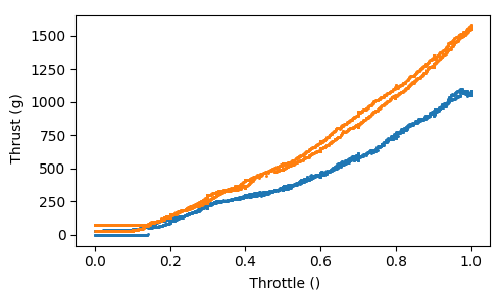
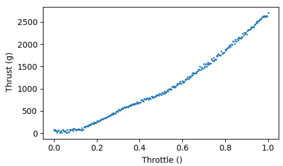
These can then be summed to give the resulting total thrust:
1 Like
I like this very much!
2 Likes
Very nice!
Outstanding attention to detail & great features.
1 Like
Is the thrust measurement bi-directional for this case? (co-axial)
As in the bottom motor will be in tractor confguration & the top motor in pusher configuration
Yes exactly. The load cells are bi-directional. You just get +/- thrust and torque to give the direction. The positive direction is set during calibration. Then I have put a little tick box in the post-processor that allows you to invert negative thrusts and torques for easier comparison.
1 Like
Thats awesome. Question: Im not quite sure how the torque cell is connected to the shaft. How is the torque being measured, if the two bushings are rigidly connected to the rest of the frame? Wouldn’t this restrict the direction of motion needed to measure any torque?
The motor is connected to the shaft. The torque load cell is also connected to the shaft. The bushings allow the shaft to both rotate and slide in the direction of the shafts axis. So any motor torque would cause the shaft to spin, if it weren’t for the torque load cell preventing the shaft from spinning. Critically, the torque load cell is the only thing that resists the shaft from spinning, hence why we can measure the reaction from the motor torque. I hope that makes sense. I will be sure to post up an animation of all the Fusion 360 joints, when I get to explaining the construction, to help everyone see how it works.
Yes, I am also not sure about the torque measure. First, I think it is more useful torque/rpm. This is a graph of a manufacturer with the curve torque/rpm
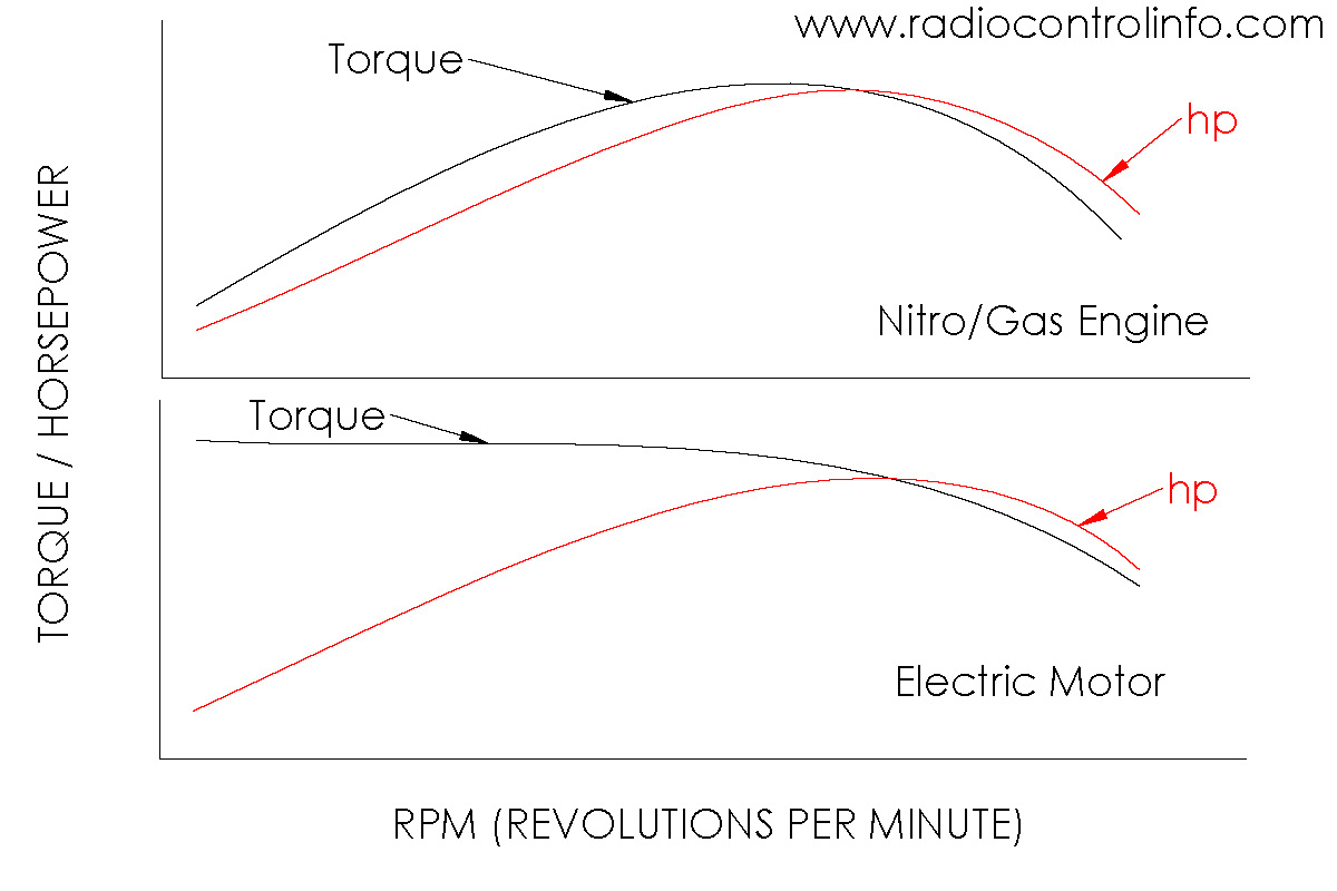
In electric motors the torque is máximum with minimum rpm, and I think you are getting a measure of the energy of the rotating system.
In adition to my post I think that your device is awsome and very well finished.
very nice!
I like this very much!
For those that are interested here is the link to the talk I gave at the ArduPilot Conference about this project:
ArduPilot Thrust Stand by Matt Kear - YouTube
For those that have been asking about how the torque measurement works, if you skip to 22:24 I talk about the torque load cell specifically.
1 Like
Hi @IAMMATT , and anyone else doing thrust measurements 
We’ve had some debate about Flame ESCs providing some form of thrust linearization - or not…
Your mission, should you choose to accept it, is to measure a T-Motor Flame ESC compared to some ordinary ESC (such as equivalent Hobbywing Xrotor) in regards to thrust expo.
It may be that you don’t even need to use a T-Motor motor and prop for tests, because we probably just want to know how different the ESCs are in this case, and if the ESC is doing anything to the thrust curve.
I think there’s lots of cases where MOT_THST_EXPO,0.2 is in use and working fine. Some say the Flame ESCs don’t do linearization and the normal calculated MOT_THST_EXPO for your prop size should be used. It would be great to put this debate to rest, or at least give it some actual data.
Hi Shawn,
I have never seen data for the flame Esc’s. However I have seen data for the t-motor alpha. Esc’s (both with t motor motors and with other brand motors). The Alphas also claim to do thrust linearization. I can tell you with certainty that they do not linearize the output. So my money is that the flames do not also.
Hi Matt, you really made a very impressive and good job.
I purchased few week ago the same Thrust Stand you started from (Mayatec MT10 Pro) and I found that the most boring issue is to write manually the measuring data (considering also the limited time due to the battery service), so looking for someone that already solved this issue, I’ve seen your post and have been very well impressed.
Now, I am not interested measuring the torque because I pilot only airplanes models, so I would be interested to do something like what you made at the beginning (the thrust stand capable to acquire thrust, voltage, and RPM from electrical commutation with the capability to input the voltage manually or with a defined step sequence and the OLED display with the capability to store data or send them to a PC.
I have not (as I suppose you had not too) the Thrust Bench pinout of the thrust reading display and/or at least of the strain gauge installed on the measuring beam.
Could you help me to make something similar to what you made at the beginning of this job? I have some knowledge and practice in mechanics, electronic and informatics also if I never worked on the Arduino World, so I hope that, with the right instructions, I could do what I have in mind (of course you help will be essential to reach my goal).
Hope that this is the right place to write about this issue otherwise please, let me know how contact you.
Thank you in advance.I will appreciate very much if you will be available to help me to transform my wish in something real.
Valter
Hi Matt, very nice project. Have you released the CAD files for the stand?
1 Like
Just posting this here for anyone who wants to replicate:
The key bit that people will need is the Lua script to get a ArduPilot based thrust stand. The lua script can be found here:
ardupilot/libraries/AP_Scripting/examples/Thrust_Stand.lua at Thrust_Stand_XL · Gone4Dirt/ardupilot (github.com)
This script is used for interfacing with this amplifier:
SparkFun Qwiic Scale - NAU7802 - SEN-15242 - SparkFun Electronics
The script is flexible enough to be used for both thrust only or thrust and torque. This is achieved through the THST_ENBL_TORQ param to use torque measurements.
The point of this script is that we can use any ArduPilot supported sensors or ESC telemetry to add measurements into our test data.
For many, a disadvantage to this method is that it stuffs all of the logged data into ardupilot *.bin files which means that for optimal ease of use, users will need to be comfortable with parsing bin files and getting the data out of them. I use Pymavlink’s parser for example. An alternative option is to export the data to matlab *.mat or *.csv using mission planner. It adds another step to the analysis process but may be easier for many users.
An idea to avoid the bin file, you could write the required data directly into a csv file with a lua script. Gives you the advantage of a better time resolution and avoids the parsing.
Yes, you are totally correct. The original version I had a few years ago had CSV logging. My personal preference is to use .bin logging because it means that the script does not need to do anything to add logging for additional sensors. Take RPM for example, it just works without needing to access it from scripting.
But the point of this script is to offer people with a good starting point. I do not intend it as a app that will fit everyone’s use case. If csv logging is preferred by a given user, it can be added by said user ![]()
2 Likes