Hi,
Truly new to this,
I am trying to enable battery monitoring on my HolyBro Pixhawk 4, however no success.
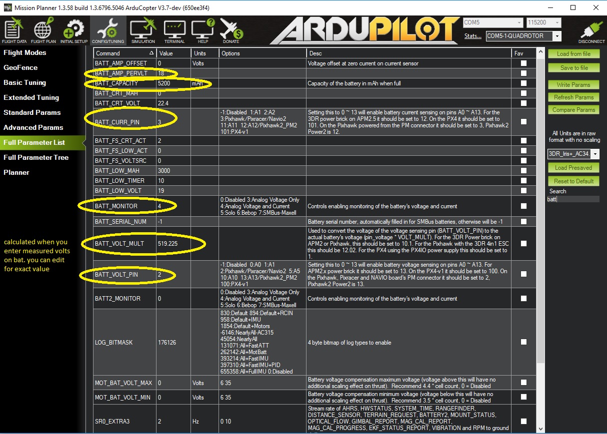
I have set BATT_MONITOR to 4 but I do not know what values I need to set for BATT_VOLT_PIN and BATT_CURR_PIN.
Any help appeiciated.
Gal.
Hi,
Truly new to this,
I am trying to enable battery monitoring on my HolyBro Pixhawk 4, however no success.
I have set BATT_MONITOR to 4 but I do not know what values I need to set for BATT_VOLT_PIN and BATT_CURR_PIN.
Any help appeiciated.
Gal.
Gal,
Welcome. For Pixhawk4 it should work if the same pin values are selected as for a Pixhawk. I think a reboot will be required after changing these values.
BATT_VOLT_PIN = 2
BATT_CURR_PIN = 3
The values should have defaulted to the correct values actually… in any case, hopefully this helps.
@rmackay9 thank you. I shall try and see what happens.
Best,
Gal
Hello @rmackay9, in the docs I received with my Pixhawk 4 and the PM07 power board, it says that the Power 1 and Power 2 ports (bricks?) have something different than what you mention here. What it indicates is this:
Pin, Signal, Volt
1(red), VCC, +5V
2(blk), VCC, +5V
3(blk), CURRENT, +3.3V
4(blk), VOLTAGE, +3.3V
5(blk), GND, GND
6(blk), GND, GND
Also, it says:
“The CURRENT signal should carry an analog voltage from 0-3.3V for 0-120A as default. The VOLTAGE signal should carry an analog voltage from 0-3.3V for 0-60A as default.”
So I have sett BATT_CURR_PIN = 3, and BATT_VOLT_PIN = 4.
I still don’t understand what they mean by the voltage part where it says 0-3.3V represents 0-60A ?? Why are they using amps here, is it just a typo? Do they really mean 0-60V? Even if this is giving the measured current across a voltage divider, how do I know what that current represents in voltage? What does the voltage divider network look like? So far I have yet to figure this out. I am using a voltage multiplier of 20560, because using the 60A(V?):3.3V ratio of 18.1818, I get 0.015V as the resulting battery voltage. So I started by multiplying it by 1000, and then adjusted the value to get the voltage I measure with a voltmeter.
But now, it seems to monitor the voltage for about two minutes or so, then it stops and stays at a fixed value. I really don’t understand these sorts of glitches. I never know if it’s me, my computer, the FC, the Mission Planner software, the firmware (3.6.0-rc6 in my current installation), or what.
Any how, is there some schematic somewhere of the Pixhawk 4 that would show how this battery monitoring stuff is actually implemented? If there is a voltage divider, and I have the values, then I can understand what I should expect to get at the pins - but in this black box, I have no idea.
Thanks,
Brad
I use Pixhawk 4, not sure about the pins you have mentioned, however here are the ones I use:
HTH,
Gal.
Thanks Gal, I was using that before, but the voltage reading never changed - until my battery went dead.
I think that Pin 2 is as I stated above, the VCC +5V regulated input voltage powering the Pixhawk, not the actual battery input voltage which is on Pin 3. If this is different somewhere in the HAL or other programming, so that “Pin 2” is just a name and not an actual pin number on the power input socket, then I think it needs to be documented to reflect what it really is.
I think you are right that it is just a name since for px4 the value is 100
hi @brad.wilkinson ,
if you have any insights on this issue, it would be great if you can share your findings. It seems like there is not much info on Pixhawk 4 as of yet (almost none) and I do have an issue with correct voltage reporting - meaning it is not correct with the aforementioned settings.
Thanks,
Gal
@gnitzan, It does appear that people use the term “pinout” in general without much explanation as to whether they mean “connector pin” assignments, pin counts on the physical board connections, or if they mean processor pin assignments. It appears that most of the typical meaning people use is referring to the board connector pin, or soldering hole, etc. But this is definitely different from board to board, and confusingly for a newbie like me, the latest Pixhawk 4 doesn’t seem to match the earlier Pixhawks or the PX4 in any of this.
It appears to me that the processor pin assignments (pinouts), which are then wired, maybe with some electronics in between, from the processor to the connector pins or sockets or solder points are described in the FMUvX specifications. And this is what I was looking for all along - something to describe which processor pin went to which connector or board pin, so that I could understand what does what. Other than the standard FMUv5 assignments that I link below, this is still not really available specifically for the Pixhawk 4 - at least not as far as I have been able to discover.
Here’s what I have found so far (sorry this is long, it’s a research post  ):
):
From the ArduPilot Copter Docs page for the Pixhawk 1, I found that the power connector pin assignments for that one are the same as the Pixhawk 4, like I listed above, where current sensing is on pin 3 and voltage sensing is on pin 4 of that connector socket.
http://ardupilot.org/copter/docs/common-pixhawk-overview.html#common-pixhawk-overview
But further down, also on this page is this:
Pixhawk analog input pins
This section lists the analog pins available on the Pixhawk. These are virtual pins, defined in the firmware.
Virtual Pin 2 and Power connector Pin 4: power management connector voltage pin, accepts up to 3.3V, usually attached to 3DR power brick with 10.1:1 scaling
Virtual Pin 3 and Power connector Pin 3: power management connector current pin, accepts up to 3.3V, usually attached to 3DR power brick with 17:1 scaling
So, the assignment @rmackay9 mentions in his first response to you that the voltage pin is “2” and the current pin is “3” on the Pixhawk matches this explanation. Then, the settings should work if that matches what has been wired internally in the new Pixhawk4. But other than just trusting this info, I have no way to verify it. I found (see explanation below) that the original STM32F4 series PX4FMU/PX4IO boards had voltage and current sensing on processor Port A Pins 2 & 3, so that seems to be where it comes from, even though the actual physical pins are not called that… , but not as much as before.
"Further Research" section:
Stuff is fairly well available for the new PixhackV5 using the latest FMUv5 - but obviously the physical wiring on these is going to be different from the Pixhawk4. A couple of things I found for these are here:
1 - on the PX4 Pixhawk4 user page, at the very bottom, is a link to the FMUv5 STM32 processor “pinouts”:
https://docs.px4.io/en/flight_controller/pixhawk4.html
2 - And on the CUAV PixhackV5 github repository is their version of this same spreadsheet, which shows some of their changes for the Pixhack:
https://github.com/cuav/hardware/blob/master/V5_Autopilot/FMUv5_stm32_pinout.xlsx
In these, I have finally found some information indicating that the Pixhawk4 and PixhackV5, using the FMUv5 style firmware, would use processor port PA, pin 0 (ADC1_IN0) for BAT1_V (voltage sensing input), and pin 1 (ADC1_IN1) for BAT1_I (current sensing input). Pins 2 & 3 here are for Battery 2. However, where these pins are routed inside the Pixhawk4 is anyone’s guess. I am guessing that they go to the power block 1 connector pins 3 & 4 as I mentioned in my first post above, and are matching the Pixhawk1 wiring plan. And I am assuming that the PM-07 power board that comes with the Pixhawk 4 does the wiring and electronics for the voltage divider and for current sensing - but I haven’t found the hard details on any of that yet, still a little
Another thing I found is that for FMUv2, for the “original” Pixhawk (1, dog-bone shape), there is a schematic available on github:
This one lists the pinouts on sheet 1, “FMU SOC Ports” as U101PortA_L, pins PA2 for voltage sensing and PA3 for current sensing, and it appears that these are also processor pins 25 & 26. On sheet 11, “Power Source Selector” it has a schematic that shows the wiring from the J601 power connector to the voltage and current sensing inputs, which confirms the “virtual” (processor) pins 2 & 3 to “physical” pins 3 & 4 linkage. So, again, to match what @rmackay9 says above, these processor “PortA” pins 2 & 3 are the ones that are monitored by the STM32F4 FMU for battery voltage and current, at least in the Pixhawk1. Now, I have to assume here that by him saying that “For Pixhawk4 it should work”, he somehow knows that the new Pixhawk4 board has the same processor port assignments as the original Pixhawk. And that would make sense to an extent, as you wouldn’t want have to re-write the code for every new board. But it doesn’t make sense to me when I see that FMUv5 says it’s PortA, Pins 0 and 1 instead of 2 and 3 (which are for Battery 2)…so now a little more
For the “original” PX4-FMU/PX4-IO board combo, which used FMUv1, the archived ArduPilot overview page has details too:
http://ardupilot.org/copter/docs/common-px4fmu-overview.html#common-px4fmu-overview
On this page it lists pin 5 of the 15-pin Multi Port row as the “Battery Monitor” pin, and also mentions that the PX4-IO board uses pin 100 for battery voltage sensing, and pin 101 for current sensing, and points to these pins on the pictures of the board. It goes on to describe pin 100 as a “virtual” pin, implying that it’s not a physical pin that you can connect to - but in the picture it points to the pin on the battery connector as pin 100. So that appears to be where the reference to pin 100 came from, even though at the processor, it was still pin 2 and pin 3…Still pretty much
Maybe we will eventually get a schematic of the Pixhawk4 from Holybro with this info detailed, so that we can know for sure. Meanwhile, I am going to keep testing my setup to figure it out as I go (first try will be by using “virtual” pins 0 and 1 !!)… 
Wow Brad thank you so much for sharing all your insights on this issue!
Amazing work.
Gal.
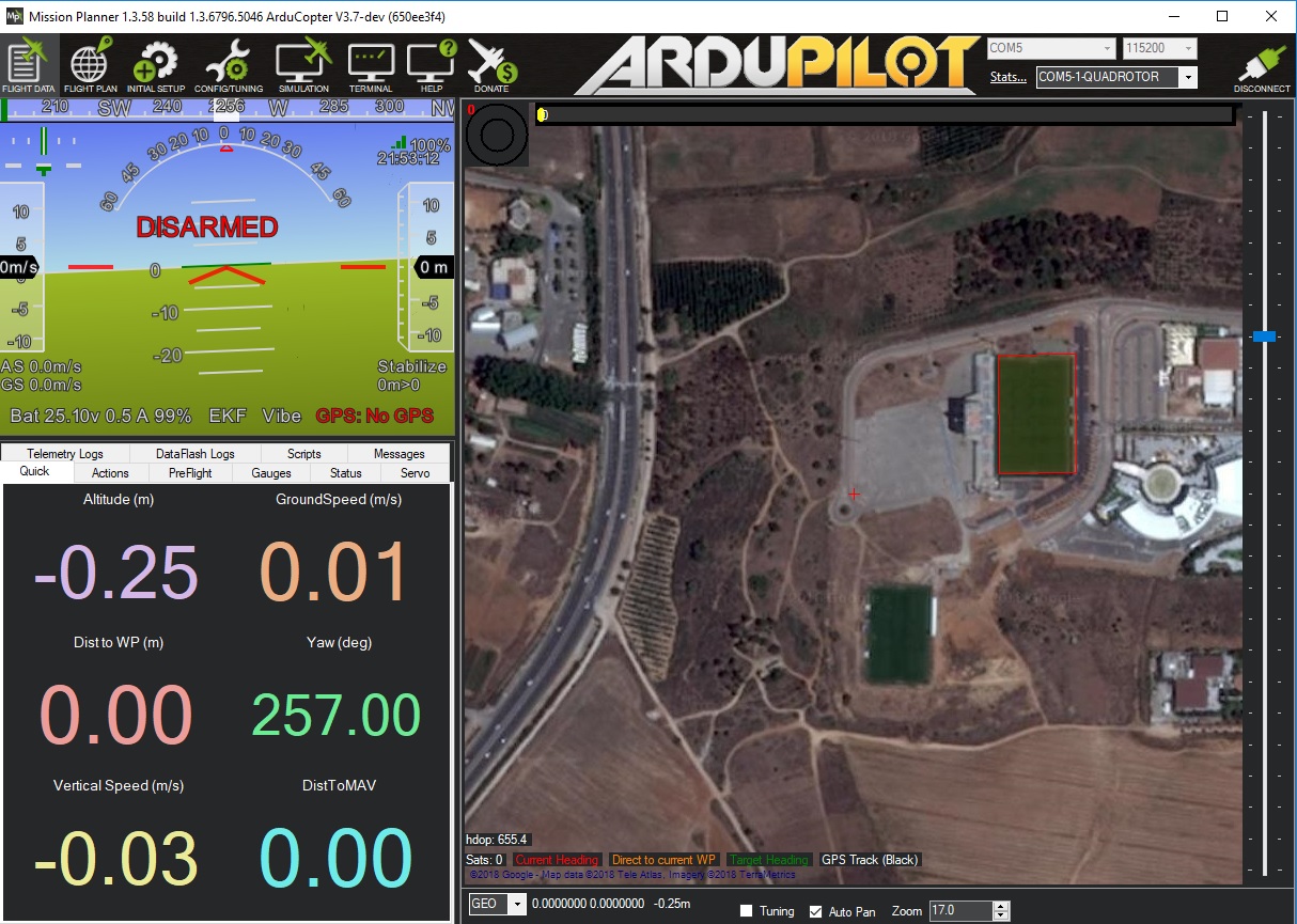
hi @rmackay9 I was wandering if you have a clue, I have an issue with voltage reading (didn’t have it on PX4 FW), however my battery reading when I fly is high. I calibrated just before the flight and MP showed correct value.
I followed the Youtube tutorial on bat calibration (without the current part - set it to 18 manually AMP_PER_VOLT)
@gnitzan, Hello Gal, that’s a great telemetry screen - how do you do that? Is that something you can get somewhere or did you do that yourself?
I have figured out a couple of thing since before - the Pixhawk4 does use “virtual” pins 0 and 1 for battery sensing, like I suspected above. Pins 2 & 3 are for battery 2. These pins are actually not “virtual” programming pins, they are the processor port PA ADC input pins, but they are wired out to the power connector pins 3 & 4 like the older schematics show. So now my settings are:
BATT_VOLT_PIN = 0
BATT_CURR_PIN = 1
BATT_VOLT_MULT = 18.182 (That’s 60V/3.3V scaling, per PM07 board instructions)
BATT_AMP_PERVLT = 36.364 (That’s 120A/3.3V scaling, per PM07)
This seems to be working just fine, so far. Hope this fixes your problem.
Brad
@brad.wilkinson Hi Brad, it seems like you nailed it !!! I just used your params and except changing the voltage devider to match my measured voltage, spot on. Well done and thank you so much for doing all the hard work .
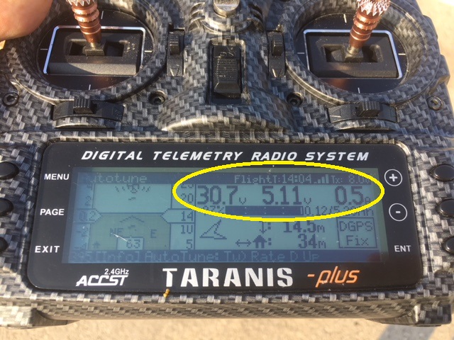
As for the Taranis’s Telemetry its actually a script combined with a telemetry cable for smart-port $10 it is called FlightDeck $24.99 from Craft and Theory site. I followed their PDF instructions, all works OOB and its great and it makes minmOSD obsolete in a way - less many cables  .
.
Thanks a lot,
Gal.
I can confirm that using BATT_VOLT_PIN = 0 and BATT_CURR_PIN = 1 works for a PM07 power modules connected to a Pixhawk 4.
Hi Brad
I have been having trouble setting up current monitoring with a Holybro Pixhawk 4 and Holybro PM02 power unit, Arduplane, Missionplanner (MP) and 6S Lipo.
Following your posts,I too have found that;
BATT_VOLT_PIN = 0
BATT_CURR_PIN = 1
BATT_VOLT_MULT = 18.182 (That’s 60V/3.3V scaling, per PM07 board instructions)
BATT_AMP_PERVLT = 36.364 (That’s 120A/3.3V scaling, per PM07)
Works best for Voltage, calibration checked with a Turnigy meter.
However, no matter what I do I cannot get the current to change. With the above settings, I get 102A in MP at 0A measured on the Turnigy meter. Running the motor up to a current draw of 10A does not change the value displayed in MP.
I have measured the voltage coming into the 3rd pin of the Pixhawk Power1 socket. This voltage drops in a linear manner as the current measured on the Turnigy meter increases. I assume that this voltage change is the raw data used by the Pixhawk board to calculate the current draw. This voltage starts at around 22.7v with zero A current measured.
I note that the current sensing pin in the Pixhawk 4 reads up to 3.3V and I wonder if it is essentially saturated by the 22V input??
Incidentally, I have a Pixwak 4 mini, PM02, Arduplane, MP set up for a different build. This measures voltage and current perfectly with the settings you posted.
I am running out of ideas. I do not know if it is possible to read the raw data as the Pixwawk sees it coming into the sensing pin. I think I could if it were my own Arduino code I was uploading to the board, but this is beyond my abilities.
I have looked at this for a few days now. If you can see what I have stupidly overlooked or have any insights it would be greatly appreciated.
Best wishes
Jonathan
Solved. After writing down my progress, it bothered me that the output from the current pin on the Holybro PM02 power module was a drop in volts for an increase in current.
To isolate the issue I used a benchtop power unit to supply potential to the Pixhwark 4 Battery Current Sensing pin, pin 3 in the Power 1 socket. Between 0 and 3.3V this shows a proportional increase in the measured current displayed in Mission planner as the voltage increases.
That finding made me question the current sensing output from the PM02 power module.
I swapped it out for another one and now voltage and current are sensed and displayed in Mission Planner.
I have spent 3 days diagnosing a faulty PM02 power module.
Better order a new one. At least I learned some things.
Jonathan
I have basicly the exact problem with pixhawk 6c , did you solve it?
If yes how?
Thank you