No I am not using Mavlink over CRSF and I think you will find it will saturate the link if you use it with yaapu. I don’t understand the compass question - just plug it in over USB and configure it, no?
Great to her that compass calibration done with USB cable is sufficient.
I had read that compass calibration needs to be done away from all sources of EMF and metallic objects. So, I have always used Telemetry radios for compass calibration, and I always do fresh calibration if flying at a new place. Additionally, I would like to send autonomous mission commands from my laptop and delve into doing the same from QGroundcotrol from an android phone, for which I thought I needed Mavlink communication. This build for me is a development platform as well as long range flying.
Oh I see. That’s easy enough - just start it with USB attached and then detach the USB. You are right that doing the calibration outside away from metal and with a good GPS lock is a good thing to do. If you have a buzzer then it will beep while the calibration is going - or LEDs will flash red/blue. I think you might even be able to use dshot sounds to know when it is done.
Thanks Andy.
Hope to get the soldering done today. Hoping your param files for this build will make an easy job for tuning the drone. Stay tuned ![]()
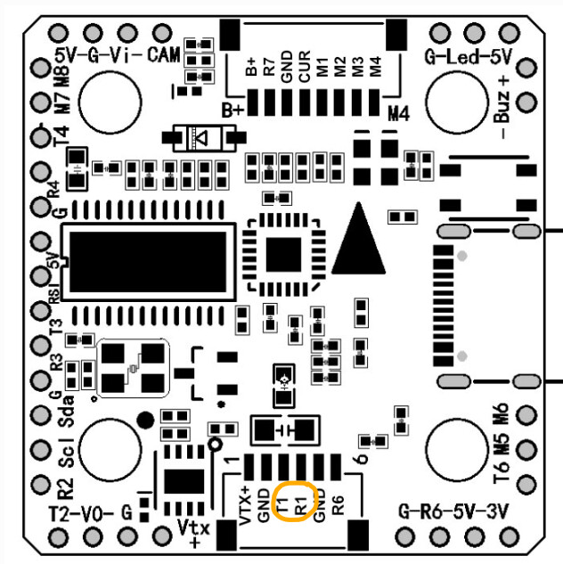
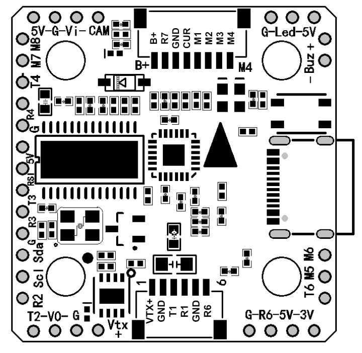
As promised, I soldered all the components. Vtx+ pad is not providing the 9V to the RX. The RX is not getting powered up. I checked the voltage for the CAM and GPS which was I found to be close to 5V. When I checked the voltage for RX and it seems to be fluctuating on the Kakute Mini 1.3 (I have 2 and both behave the same way). Here is the video. (https://youtube.com/shorts/y4pr97tN7EQ?feature=share). When I connected the RX to the battery pad directly, the RX gets powered up. I would like to take advantage of CRSF bidirectional telemetry by connecting the RX to UART 1. Any ideas why the Vtx+ on 2 Kakute mini is not able to provide the 9V to the RX. Should I just connect the RX (CRSF Sixty9) directly to the battery pads on the ESC (Tekko 32 F4 50A BLHELI_32 4in1) and the TX and RX to the UART1 as below:
Apologies for these neophyte questions. I am new old hobbyist, but I am motivated to make it work ![]()
VTX power is controlled by RELAY2 by default. If its not powering up try changing RELAY_DEFAULT
You were right on!!! Thanks kindly! RELAY2_DEFAULT was 0 by default. Changing it to 1 powered the UART to the battery voltage. Thanks once again!!
Another FPV neophyte question. My RunCam Phoenix 2 -JB Edition is connected to Kakute F7 Mini 1.3 as follows:
CAM 5V ->FC 5V
CAM GND → FC GND
CAM Video → FC Vi
@andyp1per - you mentioned in your video that you connected the CAM to R4 and T4. For my build, Runcam JB has only GND and menu pins not yet connected to the FC. Do those need to be connected to the FC R4 and T4?
Also Buzzer Question - You mentioned that you connected the buzzer to R6. Since my buzzer only has GND and 5V wires, I assumed that it was going to be connected to the + and - on the FC. Do I need to connect a signal wire to the buzzer’s 3rd pin which currently does not have a wire connected and connect it to R6? So the connections will be as follows?:
Buzz GND → FC GND
Buzz 5V → FC 5 V
Buzz signal (3rd connection) ->R6
Hi @andyp1per - My copter finally flew yesterday! Yay!!! The quad loitered well with sticks in the middle, but in loiter when pitched froward it drifted significantly to the left. Of course, I had not set up the compass orientation correct.
Need some help with that and apologies in advance for re-visiting this question raised here.
FC is facing forward and GPS/Compass is facing back and angled at -120 degrees relative to the FC. In order to get the compass orientation corrected, I will need to use the following parameters. Please advise if they are correct:
COMPASS_AUTO_ROT = 0
COMPASS_CUS_PIT = -120
COMPASS_CUS_ROLL,0
COMPASS_CUS_YAW,-180.
I was able to change the COMPASS_AUTO_ROT to 0 and COMPASS_ORIENT to 101. But I was not able to find where to add the compass_cus_pit/roll/yaw values. Do the custom values need to be manually added to the PARAM file and imported into MP?
I am using Quad X config, with FRAME_TYPE=1, Arducopter 4.5.2. My frame is a Rekon 5 clone, so the GPS/Compass mount is a bit different that required me to rotate the GPS backwards
(Non-standard compass orientation). And apologies if it sounds quite too neophyte like.
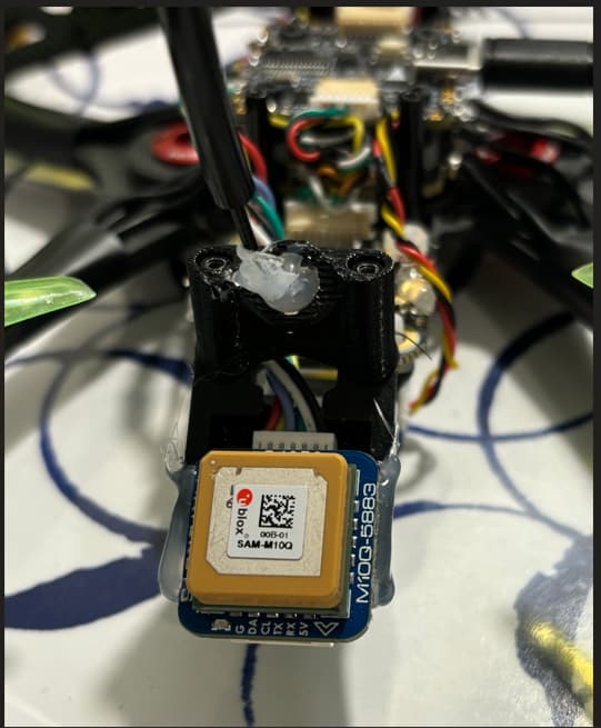
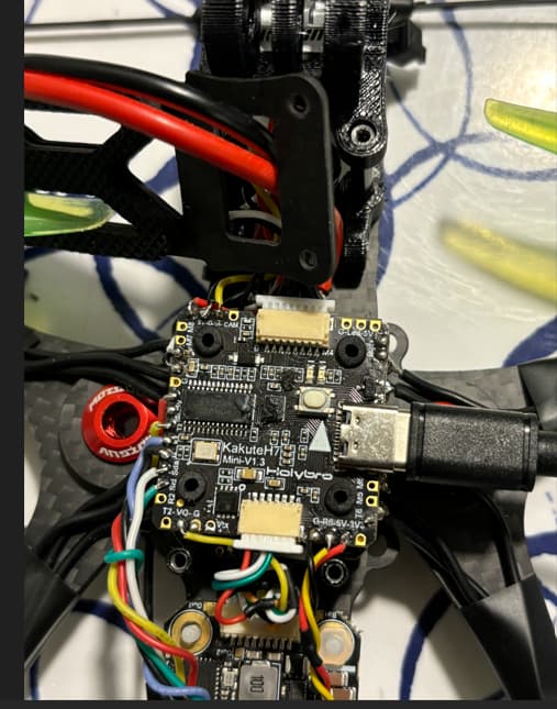
Here are some pictures.
Compass
FC
CUST_ROT_ENABLE,1
CUST_ROT1_PITCH,-120
CUST_ROT1_ROLL,0
CUST_ROT1_YAW,180
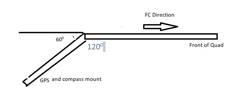
Are you sure its 120? You measure from the horizontal
Thanks for the prompt response @andyp1per .
I believe the CUST_ROT1_PITCH = -60. Please see the picture below. Am I correct?
So my parameters are
CUST_ROT_ENABLE,1
CUST_ROT1_PITCH,-60
CUST_ROT1_ROLL,0
CUST_ROT1_YAW,180
(Thanks for prompting me to reflect, it has been decades that I though in Trigonometric terms:-))
yes, that’s correct
yadadadada
Thanks kindly. Testing shortly!