Approach to provisioning a manual mode in addition to standard automation

[This thread has been taken out of Best gear for starting ArduPilot Mower]

And my initial response:

Yes… this is the part I have to learn (stick my nose in)…

I certainly have no clue about flight controller and remotes… I understand in principle the tech and signals, but not how it is being used and what it can do.
… and would need to look at what protocols are being used.
… makes sense, but does not provide the clean separation between manual and auto, as in not having to rely on any automation, GPS, and what not to control the mower maually.

Not being stubborn, my approach seems logical (to me at least :slight_smile: ), but if someone tells me the the flight controller is not at risk of failing, I’ll have a closer look.

This is definitely the area I need to spend time and rely on others to help me out (until I got it and am comfy with it).


OK, second take (After re-reading your post)…
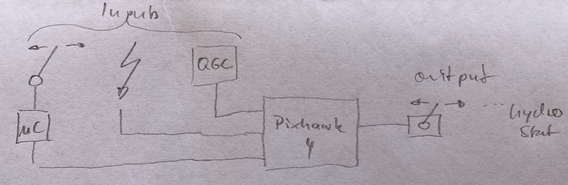
a) keep the autopilot in the loop during manual control
b) put a switch on the RC receiver signal line to toggle between the actual RC receiver and my surrogate micro-controller “receiver.” (This I don’t get)
c) keep the “flight mode” channel switched to MANUAL (I assume there is a channel for this, but what does it do; I am also not clear how many channels I even need; do I have enough with the gear I have got)
d) write code for servo drivers (this is really simple, essentially PWM)
e) switch all of their signal lines to another source (only downside to this is: I have to physically connect stuff; e.g., need connectors for it.
f) benefit of having data logging for all manual control, (that’s definitely a plus)

So what about all the safety logic; e.g., if this switch is ON|OFF, that function does work or not? Would this be programmed on the flight controller? What language? LUA?
This is where I do understand jack all.

Thinking about it again, I still think my clear separation of duty (auto/manual), where one mode does not relay on the other seems ‘clean’ to me. E.g., those who give me a helping hand, do not need to consider my ‘manual’ controller for any automation work (as long as I ensure the required pass-throughs have been catered for). I am not saying outright ‘no’, it just doesn’t click right now.

Anyway, keep it coming guys :slight_smile:

b) put a switch on the RC receiver signal line to toggle between the actual RC receiver and my surrogate micro-controller “receiver.” (This I don’t get)
e) switch all of their signal lines to another source (only downside to this is: I have to physically connect stuff; e.g., need connectors for it.

With your proposed approach, every peripheral device (servo, relay, etc) needs two connections: one to the autopilot, and one to the microcontroller. To completely separate the signal paths (as you should), you’d need a bank of toggle switches or a large multi-throw switch to transfer control.

I’d rather use a single DPDT switch to toggle the autopilot’s RC receiver input lines between an RC receiver and the microcontroller for manual control and leave all of the peripherals connected to and operated by the autopilot via RC signaling.

c) keep the “flight mode” channel switched to MANUAL (I assume there is a channel for this, but what does it do; I am also not clear how many channels I even need; do I have enough with the gear I have got)

ArduPilot vehicles are switchable between many different control modes (colloquially called “flight modes”). The active mode is selectable via GCS messaging (Mission Planner) or, more conveniently, an RC transmitter using a multi-position switch assigned via the MODE_CH parameter.

MANUAL mode is essentially RC passthrough for all channels, which is the mode you’d use for ride-on manual control and/or for unassisted RC control via the transmitter (no course/speed assistance as in ACRO or STEERING modes). The microcontroller’s RC output for that channel would be fixed to MANUAL mode to ensure constant, unwavering RC passthrough with no chance to accidentally select an automated mode while you are onboard.

d) write code for servo drivers (this is really simple, essentially PWM)

Simple to do poorly. Harder to do well, since many microcontrollers have limited timers for use with precise PPM signaling (Arduino, in particular). You can use a servo driver board to abstract that away, but that often results in a loss of resolution.

Much easier to read encoder positions and output a single serial stream of channel states. Most RC protocols are just some flavor of serial communication. ExpressLRS and Crossfire share a common serial protocol that shouldn’t be hard to implement. SBus uses an inverted serial protocol that is frustrating to replicate on certain microcontrollers, so I’d not use that one.

So what about all the safety logic; e.g., if this switch is ON|OFF, that function does work or not? Would this be programmed on the flight controller? What language? LUA?

Probably a combination of physical switches (emergency stop that physically kills power, for example) and microcontroller code. I can envision a microcontroller-side failsafe where any anomaly (like unexpected input range or signal loss) would slew the motion control servos to neutral at a rate that wouldn’t eject you from a sudden stop. There could also be logic to disarm the autopilot (which zeroes and disables the throttle outputs) if the brake is applied, the control arms trigger the neutral switches, or the seat switch is open.

I’d keep most, if not all of the manual control logic on the microcontroller. There may be a few odds and ends where Lua scripting on the autopilot could help, but nothing comes to mind right away.

E.g., those who give me a helping hand, do not need to consider my ‘manual’ controller for any automation work (as long as I ensure the required pass-throughs have been catered for).

No one would have to care. The autopilot and firmware would be unmolested in either approach. With my suggested approach, you’d just have an extra set of RC receiver lines that wouldn’t matter in the least to anyone attempting to help solve an ArduPilot related issue.

if someone tells me the the flight controller is not at risk of failing

I have experienced ZERO autopilot failures that weren’t directly my fault for doing something stupid like shorting a pin with a misconnected ground/power wire. Those failures were immediate, embarrassing, and not something that would happen during routine use. So I have faith that routing the signals through the autopilot solves more problems than it creates.

Lastly, for those reading who may be scratching their skulls at the discussion of manual/automated control, please reference post 6 by Randy on this topic.

Consider, also, that if you control each servo directly via the microcontroller and then switch control to the autopilot, that you have two sets of min/max/trim values to manage.

Anytime you adjust linkage (for wear, for example), you’ll need to readjust both the autopilot servo parameters and the extents programmed into your own code (likely requiring a re-flash of your microcontroller).

Much easier to manage that once…on the autopilot.

1 Like

Alright… :slight_smile:

Thank you for your detailed reply! (and I appreciate the patience)

After some thinking I thought that it would be best to leave the manual control out of the picture for this automation effort.

Behind the scenes: I will continue with the micro-controller for the manual mode, as it will offer me a bunch of advantages, which I will detail once I have this thing in operation (and proven it works).

All it has to do is switch six servo lines (over to automation), which is irrelevant for the ‘automation’ work or configuration.

As for adjusting trim values, these are either updated via WiFI/MQTT on start or written to EEPROM. I also thought about a ‘calibration mode’ function (which presents no grade of difficulty in this space).
[Didn’t see a need for it until someone pointed out temperature-influenced differences.]

Technically, it’s possible to connect another set of serial lines to your microcontroller to receive MavLink telemetry from the autopilot, which gives you a wealth of data, most of which would be irrelevant…but you could retrieve the servo parameters that way. Requires quite a bit of flash space for the requisite libraries along with some non-trivial coding.

Get the automation working first - great approach! Get comfortable with the ArduPilot ecosystem and then roll the manual stuff in later. You may find more value in my suggestions once you’ve used it a bit!

1 Like

I really hesitate to get in this conversation but I don’t think you want to lose sight of the fact that you will need both systems powered up when you are out there driving around in manual and marking waypoints using Ardupilot (setting up the next mowing job. It seems like removing the signal line going to the servos from Ardupilot during the manual operation is a good thing. Ardupilot can’t do anything bad without the servos.

Pretty easy to save waypoints with either approach. I actually use a Lua script for tracing perimeters, and it would work regardless of the type of control in use, so long as the AHRS is aligned with a good GPS fix.

Don’t be shy :slight_smile:

I appreciate any feedback… as I am literally “green”, when it comes to this whole RC business including related software. Hence, why I am sure there is lots of stuff I haven’t got a clue about; as in, what is possible.

That’s a good point, and something I wanted to do / achieve…
Drive the mower and collect fence line way points; and trees, and put a radius around it… or similar.

Again, I have seen small changes to date with temp but just about the “noise” level. (I got the mower tuned in winter (40’s) and now it in the 90’s). I’d do expect them to become more noticeable after LOTS of hours but not something to be concerned with now. The tuning you arrive at and your machine response might easily negate this issue completely. Just something to be aware of. Drastic changes in engine/pump RPM is another matter. Onward!

I was thinking about the hardware to switch all your signal channels from each servo back and forth from the 2 sources and thought about a relay bank that I just bought.
It is actually meant for using PWM signals coming from an RC receiver to power the coil of each relay, that is what I bought it for. However, it would work the same if you put a DC voltage on each coil, that relay would activate. Each relay has a closed contact and an open contact. If you powered all the relays at once you could cause them all to switch. I saw this relay bank like this on @ktrussell s mower and bought one from https://czh-labs.com/ I try to grab on th good ideas when I see them.


They also probably sell other relay banks that are not PWM relays.

1 Like

That induces 6 points of pretty critical failure. It’s not a bad idea, but it’d take some convincing to have me agree it’s a great solution.

Also, with this complete divorcing of manual vs autopilot operation, any added feature (like a towed sprayer, for example), would require additional IO multiplexing.

Again, simply having the microcontroller output an RC stream makes that pretty trivial. You’d only wire whatever device to the autopilot in one place.

Even the simple things like saving waypoints become simpler. You wire a momentary switch to a microcontroller’s GPIO pin and toggle the SaveWP channel in the RC output stream.

Sure, you could configure a SaveWP GPIO button directly on the autopilot and still maintain the “divorced” paradigm. But now you’re using up precious autopilot GPIO for a function that’s ostensibly doubled as an RC function as well. Or you could put the RC transmitter in your lap and toggle the SaveWP channel with it directly, but that sounds silly!

ArduPilot supports onboard displays, as well, on the I2C bus. The only supported ones are pretty tiny and don’t display much info, but it might be a nice, cheap addition to have onboard, regardless.

You have me convinced Yuri and I agree with what you are saying. If you wire the RC stream from the microcontroller into Ardupilot does it take the place of RC stream from the RC transmitter?

Correct. One or two wires to toggle (depending on RC protocol) rather than every single device. Think of it as if the control arms, ICE throttle, ICE choke, PTO switch, etc are all just creating a big onboard RC transmitter for direct control of the machine with the autopilot set to MANUAL mode.

Pros: significant flexibility with simpler wiring and fewer points of failure.

Con: the autopilot becomes a single point of failure.

Note that I didn’t mention the autopilot remaining in the loop during onboard ops as a specific disadvantage. Any risk there is mitigated via appropriate failsafes/emergency stop(s).

Agree with Yuri… no relays, but rather signals.

Where do I find info about the protocol?
What protocol is it? (MavLink?)

What I have noticed so far, is that I struggle with inputs to the pixhawk.
As above, what protocol?
How best to talk to the pixhawk?
If I have to figure this out myself, I may pick the wrong approach, given the little (to no) knowledge I have with this RC topic, and it may take ages, and potentially turn out unsuccessful or overly complicated.

Given the topic, and my propensity to stick with a manual option, I can see ‘creating’ input signals for the flight-controller to digest. E.g., the micro-controller is always on, providing ‘clean’ signalling of already digitised input signals.
This ‘clean’ signalling could be a simple high|low, 0|1, ON|OFF, or symbol (a bunch of bits or bytes), meaning the flight-controller takes the micro-controller as inputs.

This would mean the flight-controller needs the micro-controller, but not the other way around.

I have not trouble building e.g., a sensor, and determine its output; here (below), a linear motion sensor taking the movement of the control arm damper of a mower, and turning it into whatever I want; e.g., 0-4095, 0-360 degrees, 0-100, etc.

… but the trouble I have is, if using the flight-controller as the heart for both auto and manual, what does this signal need to look like, what protocol and ports to use, to get this into the flight-controller?

That is a very nice looking part and such a good idea! We will have to get the protocol details from Yuri, but to my understanding it is not going to be anything as complicated as Mavlink. It will be some sort of RC protocol, but I am still trying to understand Yuri’s plan. I think the microcontroller needs to mimic what would come out of an RC data stream. I will work to understand this and help you out.

In short, my suggested approach uses exactly ZERO of the servo/GPIO pins on the autopilot. If ANY approach were to start using up I/O pins on the servo rail for a scheme like this, I’d call it extremely flawed.

You’d use a UART (like SERIAL2, which is labeled Telem2 on the Cube carriers) to receive a serial stream from the microcontroller that contains all channel data in the RC protocol of choice.

Technically a similar approach is possible via microcontroller-based MAVLink (the bi-directional telemetry protocol), but you’d be using RC override messages which have some limitations, and the code would get bloated quickly.

  1. What is the protocol of choice? (I can’t make this call, as I do not know any, let alone the best one to pick based on the use case.)
  2. What does the data format over serial look like? E.g., frame composition.

Thinking out loud…
If I want to use my control arms as input for the flight controller for the manual mode…

  1. how can this be achieved?
  2. Would the control arm sensor plug into the flight-controller?
  3. What data format would the flight-controller expect? Serial (if I understood correctly) What does the flight-controller want to see? It would need an identifier for the sensor and a value in a certain range? Checksum?
  4. Can the remote actuate the same motion for the hydro-stat?
  5. And I assume the automation sends the same signal and value range?

See picture… (I may have this conceptually wrong; and as long as I do, any approach is futile)

The inputs above are (left to right): a signal from a sensor suitable for the pixhawk; a remote controller (RadioMaster, etc.); QGC = QGroundControl; I reckon in form of a mission.
The pixhawk has a servo connected to it controlling the hydro-stat.


If my ‘manual’ input complicates things, we can leave it out for the moment. However, I still need to understand how this all works, to later ‘splice’ in the signal from a ‘manual’ controller. — As you suggested: to use ranges (trim values) in the flight-controller.

Again, keeping it simple, the autopilot expects RC receiver input. Period. That’s it. That’s all. One signal.

The control arm encoders (and any other onboard switch, button, dial, etc) feed the microcontroller. The microcontroller translates it to RC.

I recommend ExpressLRS. It’s well documented.

Also, don’t use QGC. It’s meant for PX4, despite that it technically connects to ArduPilot. Use Mission Planner.