Approach to provisioning a manual mode in addition to standard automation

Thanks… I hope I do not sense frustration… this is all new to me.
And agree, keep it simple.

OK, got it… :slight_smile:

Will read up on it. Thanks.

I have a RadioMaster 16-channel remote, and 915MHz Holybro Telemetry radios.
Just watched a YT and it seems this radio link comms software.
… which leaves me with two questions:

  1. Why would I change the radio link software; mine is working. What benefit is there? Do I have to fiddle with this in order to automate the mower?
  2. I am back to my question of what data/frame format I have to produce (post sensor) to feed into the flight-controller? Looks like I am missing something.

I have not preference; maybe I mean Mission Planner; happy to use what everybody else is using (or you suggest).

You said for the “PX4”. does this stand for ‘Pixhawk4’? If so, this is what I have got. Do I need to get a different flight-controller? If so, which one?

Your Orange Cube is fine. The PX4 is a designation used by an older version of the flight controller. I have been reading the posts and thinking this through and I understand the approach that Yuri has proposed and I really think it is genius.
I also have done some searching around and other people have used the Arduinos to create an ExpressLRS data stream. You should be able to find help and references on doing that. So to me this means that your microcontroller will have to drive your servos by however you are controlling them and also simultaneously create the ExpressLRS data stream that can be switched into the wire going from the existing RC receiver and the Cube. I really think this is ground breaking and will help others in the future.

Some minor corrections:
PX4 is a completely different firmware project. None of us use it.

The Pixhawk 4 (if it is the one by Holybro) is probably ok for the application, but it uses an older processor and has less flash space than the H7 based autopilots that most of us use (like the Cube Orange or MatekH743-Wing). If it were my own project, I’d replace the Pixhawk 4 with a newer model.

Sorry, I mistakenly thought you had an orange cube.

No. With my approach the RC (ELRS) serial stream is what tells the autopilot what to do with the servos. They remain connected to ONLY the autopilot.

I will draw a picture later because Max senses correctly that I am getting frustrated repeating myself.

Maybe this helps?

The DPDT switch dictates whether control is provided via the onboard mechanical levers/dials/switches or via the RC transmitter for automated operation. Actuating that switch is effectively the only thing required to switch from onboard manual operation to fully autonomous mode.

The connecting lines depict signal paths - it’s certainly not a fully detailed schematic.

Also, I’m not intending to endorse or recommend any particular brand or style of hardware (that’s for another discussion) - I just used simple graphics to get the point across.

And, while I am indeed advocating the use of ExpressLRS, any RC protocol could be used, but it should probably be common between the RC receiver and the microcontroller. ESP32s (among a few others) can even produce the weird inverted serial protocol used for SBus without additional hardware.

Clicking on the picture should enlarge it a bit if it’s too small.

1 Like

That is great picture Yuri. I understood that that the servos and relays are always physically moved by the flight controller but I did not state this correctly.

Firstly, as I stated a few times: I am a complete novice when it comes to RC control. And I mean complete! I have no clue what tech I need; yes, I get sender/receiver and the principles of it; e.g., RTK, GPS, can upload firmware, push button here, blah, etc., but still, have no clue what language / data format these things talk.
So for those already heavily in this game, potentially for years, it may well be difficult, to ‘talk’ to a guy like me.

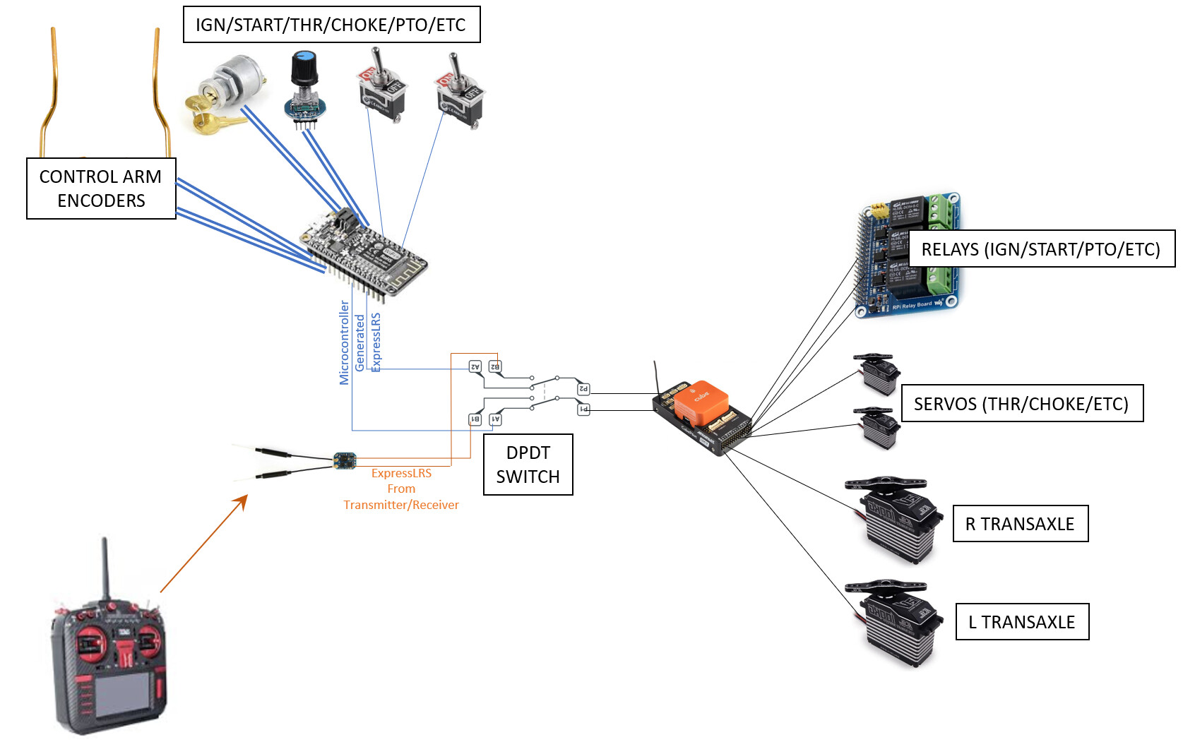
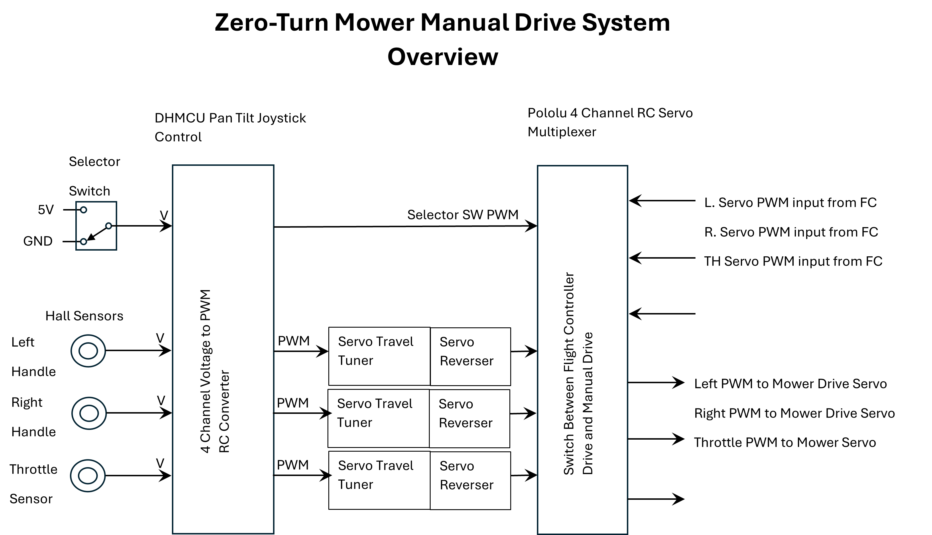
Secondly, I appreciate Yuri’s diagram; very clear now… in essence: the signal path is switched over. Yes, thanks; now I am clear on that.

So, from what I gather ExpressLRS is a transmission protocol.
Be it faster; why would I care? Or is there more to it? E.g., better (Lua) scripting, or other form of manipulation?


Excursion:

In January 2021 I wrote on this forum, in a post querying what I need to start off with a Rover, and announced, based on the input I had received, the following

I a couple days later I bought thr ArduSimpleRTK kit.

From my perspective I bought all this gear, which, due to my own circumstances, has been sitting around doing nothing for two years, and is now obsolete. Ouch! :frowning:

Does anyone know if there is an upgrade path for these RadioMaster bits to run eLRS on it?

As for the Pixhawk4, can I use it, or is it useless (e.g., in the sense it makes help less probable), as it does not have the memory/CPU do to the job? If it isn’t, I am in for another 1,000 AUD plus to replace it.

It was said the pixhawk4 would potentially work. Assuming I remove the manual control from the equation, then the remote (which I wouldn’t use; why would I? I thought I upload a mission and the mower executes it.) Would this not remove the need for eLRS?
Or do the Lua scripts that are needed to automate the mower need eLRS.

If the answer is “replace” the pixhawk4, which one do I need?
Is it this? Which is named HEX Cube+ PIXHAWK2 Flight Control H7 Orange cube

image

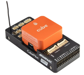
… found here: https://www.aliexpress.com/item/1005003749646742.html

Can I upgrade the RadioMasterTX16S? With what?
I have seen “Radiomaster Ranger ExpressLRS 2.4GHz Micro Module with PCB v1.6”; not sure where it goes; it costs 90 AUD.
I assume this changes the RadioMaster to use 2.4GHz?!

Can the Holybros 915MHz be upgraded? I assume they need to in order to ‘talk’ eLRS?! Do they need to, as these are for the telemetry link?!


Reminiscing on all this: the key question in my mind is "other than switching the radio protocol to eLRS, what other benefits would I get by switching, other than speed of transmission (which I do not see as an issue)?

To conclude, I am not arguing, I am seeking to understand. :slight_smile:

We can now continue the discussion based on a set-up without a manual operation requirement.

[Main reason for that is: it is a new protocol I have never worked with; I don’t have time for ATM (read-up, tinker, etc.); and it has only complicated matters for the purpose of ‘sole’ automation. However, I will tackle this at a later stage, and based on what I know now, can solve this myself as it is familiar territory apart from being a new protocol.]

I communicated with Yuri and we both agreed that the Pixhawk 4 will work just fine and Yuri said it even supports scripting. It’s just not the best flight controller to recommend to a new user. Your case is different and what you have will work. It’s not as capable as the newer models and if it becomes limiting later on it can be replaced. Waiting to tackle the remote operation by the new method is probably best for now until you learn more. Also. I think others will try this soon and we will all learn from that. If I wasn’t so busy this summer I would do it.
The starter kit you bought from ArduSimple likely has an SimpleRTK2B GPS board and a GPS antenna and you can use them, but you will need a second SimpleRTK2B GPS board with an antenna for the moving base. Please check on what you have in that kit.

Slowing down and taking this big project on piece by piece will be better.
Meanwhile I would order the remaining parts you need and do a benchtop setup with the Pixhawk 4, the radio transmitter/receiver you have, and the servos to to achieve servo movement on the benchtop. The control will be coming from the RC transmitter and going through the Pixhawk 4 set in manual mode using Mission Planner. That sounds simple but for a new person there is a lot to learn and a lot of things to marry together, including the Pixhawk 4 and your windows computer using Mission Planner. At first I would start out with the Pixhawk 4 connected to your computer via a USB cable and then later I would also integrate the SiK telemetry radio into your test setup and remove the USB connection. Even integrating these pieces together is a step by step process and you will learn a lot at each step. This is all spelled out in the Setup guide on the Ardupilot WiKi for rovers First Time Setup and Configuration — Rover documentation
Also since this will mainly be a mower building discussion we will move it back to the Best Gear for Starting Ardupilot thread so the other builders will benefit.
https://discuss.ardupilot.org/t/best-gear-for-starting-ardupilot-mower/

I’ll caveat that “best” is extremely subjective here and not the word I would choose.

The only drawback to using the Pixhawk 4 is its slightly reduced processing power and RAM vs the H7-based hardware that most of us have been using. That shouldn’t be much of an issue at all.

Get started. Get your hands dirty. Build something. Many of the things that are confusing will become clearer once you depart the realm of the hypothetical.

Yes, I have a base and rover, plus an extra one for heading.
I probably have to calibrate the base station again, given two years have passed since I did it last time, and the Australian Plate is moving about 6.858 cm (2.7 inches) a year in a northward direction and with a small clockwise rotation.

I was never in a hurry, but like to understand where I am going and what I need before I dive into this, Imagine I’d build a house by pouring the slab, and once the roof is up, I figure I need three more bedrooms. :slight_smile:

However, I get what you’r saying :slight_smile:

Done. Can see the rover, getting RTK feedback. I will connect small (toy) servos to it, which should work, until my big servos arrive.

Sure :slight_smile:

Is this a ‘best gear’ or a ‘building’ threat?! (Though happy to go back there.)

The conversation is moving back to Best Gear for Starting Ardupilot thread for now. Maybe we need to to have a better name on the thread of create a new thread. That’s just where the conversation started.

@Max_G, @Yuri_Rage I noticed that you can but fairly inexpensive converters to change the PWM pulses going to the individual servos, (like the Arduino would be generating) and converting it to the single wire serial data stream PPM format. If it worked, it would make the task of doing this much easier. It seems likely that the flight controller would recognize the PPM format. I am not an expert on this stuff, but I am good at finding things.

It would get you around building additional circuitry and writing code for the Arduino to do the conversion.
https://www.amazon.com/QWinOut-Performance-Convertor-Interchang-Multirotor/dp/B0999F7SFX/ref=sr_1_5?crid=2WEUH8PJHF3VY&keywords=PWM-PPM+converter&qid=1685807506&s=amazon-devices&sprefix=pwm-ppm+converter%2Camazon-devices%2C1330&sr=1-5

1 Like

Indeed those could be used (and induce another point of failure) on a system where the servos connect to the Arduino.

I’ve been recommending against that all along for a multitude of reasons.

I was thinking that the drive handle position sensor signals would be processed through the Arduino with a servo driver to generate PWM pulses for each servo channel. Then the output wires from the Arduino that would have normally gone to the servos would only be connected to the inputs on the PPM converter. There is always the converter in the circuit when the new ICE (Interactive Connectivity Establishment) switch is in manual mode. The PWM to PPM converter would only be a liability when the selection was made to drive with the original mower drive handles. In that mode the PPM signal generated based on the mower handle position sensors would be routed to the FC. When the ICE switch is moved to the normal position the PPM signals still come from the RC receiver and are not going through anything extra. This is an interesting problem and I think your single wire approach to the FC is really smart. I also would hope that the little converter would be fairly robust since it is a solid state device with no moving mechanical parts.

1 Like

Thanks Steve, for posting this option.

It is indeed an option I will look at.

Yuri ‘painted’ the picture (further above) about what I envisage to do, in order to maintain both, manual and autonomous driving modes.

I have put this idea on the back-burner (not abandoned), as I have only limited time to achieve a minimal viable product (MVP). This means, I want to achieve the ‘autonomous’ part first, and then build the manual mode. The idea is to use an Arduino MEGA to read the sensor signals from the linear sensors connected to the drive arms, and condition the signal to something the flight controller can read.

Instead of the relay I will use the digital equivalent (e.g., 74HC125, CD4503, 74244).

I agree with Elon Musk, that the best part is no part, which goes along with Yuri’s concern of additional failure points. However, I find this a minor issue compared to the major benefit of being able to drive the mower as ‘normal’ with a flick of a switch.

In fact, the mower’s default mode is manual. Drive it out of the garage, drive it around any obstacle, and explicitly switch it to ‘auto’ for ArduPiolot to take over the machine.


Why am I going for the MVP?

I have started owner-building a house a few years ago, which is half-finished (frame, roof, cladding, no interior), and promised to my wife that I will dedicate my time fully to the completion of the house from July 1st. I will have one day off per week from house-building, which I will use to implement the ‘electronified’ manual mode.

My present approach to switch between the two modes is to either hook-up the hydro-stat to the servo or the manual arm inputs. For auto, I simply unplug the seat switch and short-circuit pins 1 (white/black) and 4 (white), which mimics a person sitting on it.

I know you’ve put this on the back burner, and you truly need to.

Quite honestly, neither of you have the foggiest what I’ve been trying to convey.

:slight_smile: Why not enlighten us?

I am sure you’re aware I truly appreciate your input and guidance; in fact many do, based on what I am reading on the forum.

I probably should have said something here before:
I agree with your points, except, the Arduino will not connect to the servos. It will produce the PPM signal for the flight-controller, for it to control the servos.


So, please explain why I do not get you. I have taken off the ‘manual’ (electronified) approach, and am solely working on the MVP of a flight-controller-based autonomous mower.

I ‘get’ the added potential for issues any ‘part’ will introduce to a system. So what am I missing?

From what I have read on the forum, others also want to use the mower manually/normal, in addition to the automation.

You may have seen from the screenshots I posted, my property is not a “square lawn”, but presents quite some challenges, which, at least at the moment, I believe, require manual operation of the mower… even worse, I have to use an electric push mower to go around, or rather between the fruit trees, my wife planted to closely. :frowning:

I’ve been trying very hard. And I’m out of patience for the moment.

Your last response indicates a bit better understanding than I realized. But I think using the autopilot for a period of time will help crystallize the points I’ve either failed to make, or you’ve failed to grasp thus far.

I just wanted to share the manual drive system that I created for my gasoline powered zero-turn lawn mower. My mower is the typical Ardupilot converted large zero-turn mower. It is a Hustler Raptor SD 54 inch mower, but this manual drive system could be implemented on any of the Ardupilot zero-turn mowers that have the mechanical drive handles. My goal was to use the mower in the automatic Ardupilot mode and then after the big areas are done, then drive the mower with the original drive handles to finish the more critical mowing. The system I have put together using commercial parts allows me, with a flip of a switch to change control of the servos over from Ardupilot control to the onboard mechanical drive system. I configured the multiplexer switch to recognize the flight controller as the (Master) and the manual drive system as the (secondary or slave system). In this configuration it always defaults to the flight controller as being in control, unless manual control is intentionally selected.
The main components of the mechanical drive system are the Hall Effect Rotation sensors on the drive handles, the 4 channel voltage to PWM servo card, and the 4 channel RC Servo Multiplexer switch. The Pololu 4-Channel RC Servo Multiplexer can be used to allow easy switching of servo control between two independent sources using a separate PWM channel as the input selector. In this case I multiplex between the Flight Controller PWM output and the manual servo controller, which allows switching between autonomous and manual control of a set of servos.

A key to this system is the robust little hall effect rotational sensors. Here is a picture of one of these small sensors assembled.


Rotary Hall Angle 0-90 Rotation Sensor 0-5V Rotary Hall Angle Non-contact 0-90 Degree Angular Torque Rotation Sensor 0-5V | eBay

The hall effect rotation sensor is clamped with pinch clamp, allowing rotation for setup and positive clamping after installation. I found the thin phenolic adjusting plate supplied with the sensor to be inadequate in being sturdy enough and lacking adjustment range.

Here is the sensor installed on the right mower handle.


The throttle handle is also equipped with a hall effect sensor so the engine speed can be controlled by an onboard operator (normally the RC transmitter controls the engine throttle through the flight controller. The electrical systems are configured so that an onboard operator can also control the starting of the engine, mower blade PTO engagement, and have the safety interlocks back operating as they came from the factory (including the seat interlock).
The mower has a pretty amazing feel to it. With the gas dampeners still installed on the handles, it feels like a normal manual drive system.

Zero-Turn manual drive system parts list

Rotary Hall Angle 0-90 Rotation Sensor 0-5V Rotary Hall Angle Non-contact 0-90 Degree Angular Torque Rotation Sensor 0-5V | eBay

6mm Flange Coupling, Shaft Coupler QCQIANG 5PCS 6mm Flange Coupling, Motor Shaft Coupler, Flanged Shaft Mount, for DIY Handmade Model: Amazon.com: Industrial & Scientific

Servo controller card, pan tilt joystick control Amazon.com: servo controller DIY device pan tilt joystick control : Video Games

4-Channel RC Servo Multiplexer Amazon.com: 4-Channel RC Servo Multiplexer : Toys & Games

RC Servo Signal Reverser Amazon.com: 3Packs RC Servo Signal Reverser Rotation Inverter 3.6V - 24V 5A Steering Gear Reverser for JR Futaba Aircraft Airplane Steering Gear and Any Servos : Toys & Games

Servo Travel Tuner Amazon.com: Servo Travel Tuner : Toys & Games

Toggle Switch ON/ON DPDT 6 Pin 2 Pos TWTADE 3 Pcs Toggle Rocker Switches ON/ON 6 Pin 2 Position Latching DPDT Heavy Duty 16A 250VAC Spade Terminal Metal Bat Switch with Waterproof Boat Cap and 6.3mm Terminal Wires TEN-1321MZX-B202: Amazon.com: Industrial & Scientific

Julet 3 Pin Cable/Waterproof F Connector Julet-Connector 2,3,4,5,6Pin Cable Waterproof Connector For Ebike Display | eBay

Julet 3 Pin Cable/Waterproof M Connector Julet Small Connector 2/3/4/5/6 Pin Cable Waterproof Connector For Ebike Display | eBay

DC 12V To 7.5V Power Step Down Supply DC 12V To 5V 3.3V 3.7V 4.2V 6V 7.5V 9V Power Step Down Supply Converter For Car# | eBay

Throttle Cable Compatible with Hustler Amazon.com : GardenP+ 601096 Throttle Cable Compatible with Hustler Raptor SD and SDX Years 2019 and Prior, Lawn Mower Drive Control Cable, Replaces OEM 601096 : Patio, Lawn & Garden

5mm Female RH Metric Threaded Rod End Female Right /Left Hand Thread Rod End Joint Bearing Metric M4 - M30 All Sizes | eBay

M5 A2 Stainless Steel Fully Threaded Rod M2 to M20 A2 Stainless Steel Fully Threaded Rod Bar Studding, Length 150mm-500mm | eBay

Here is a link to a KiCad schematic of the overall system that I drew up. It was actually my first KiCad schematic and it took a little learning, but it was well worth the effort. Since then, I have done other schematics and I am glad I took the time to learn the application (at least at an elementary level). The schematic of the drive system is a PDF and is drawn to a fairly large scale. It will require downloading and zooming in to see the details. I printed out my work copy on a large format printer. KiCad Mower manual drive system schematic_121424_NB.pdf - Google Drive

Here are links to all the documentation I could find on the 4 channel servo controller and the 4-Channel RC Servo Multiplexer.

DHMCU Servo controller Documentation DHMCU Servo controllerl Documentation.pdf - Google Drive

Pololu RC Switch User’s Guide Pololu RC Switch User’s Guide2.pdf - Google Drive

I’ll also be happy to share details of my machined mechanical parts after I get them sketched up, although they may differ from mower to mower because each mower is a bit different.
I also learned a lot about setting this system up, which I will also be happy to share.

1 Like