the AS will dynamically change, around it is value (usuallly 1,xx or 2,xx m/s) even the aircraft is on the ground and not moving.
there is a drop down list on Airspeed setup under initial setup page. try to play with it.
the AS will dynamically change, around it is value (usuallly 1,xx or 2,xx m/s) even the aircraft is on the ground and not moving.
there is a drop down list on Airspeed setup under initial setup page. try to play with it.
I tried the following:
Inside MP, Initial Setup, Then Air Sensor. I have selected;
a) Pin = Pixhawk Analog S Port which is basically same as parameter ARSPD_USE=11
b) Type = Analog Which basically changes the value of ARSPD_USE to 1 (Shouldn’t this parameter be set at 0?)
So far, no value changes inside the MP HUD.
Pixhawk analog airspeed on the ADC connector.
ARSPD_USE 1
ARSPD_PIN 15
ARSPD_TYPE 2
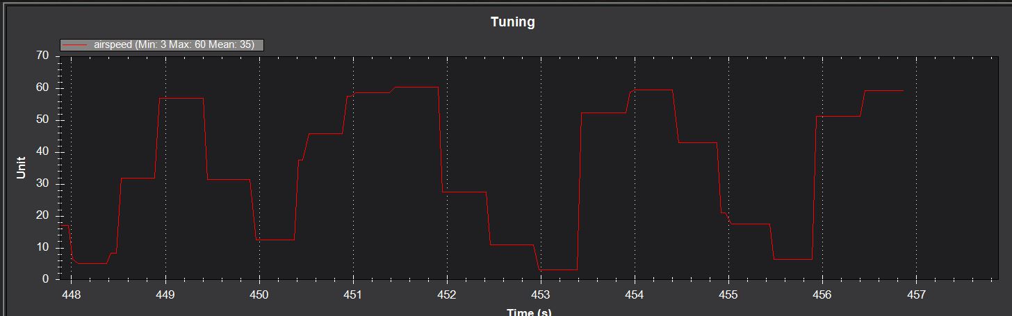
Look at it go with a few puffs of air:
So it is working now ?
Sure it works. I have had analog sensors on planes but not much reason to use them today.
Mine still doesn’t work. How did you create the above graph? what are the steps?
Not much use, how else do you know what the airspeed is? Or do you only fly in still air?
Analog sensor, not airspeed sensor in general. But that said you don’t need an airspeed sensor. Some planes I have used them, others not.
From Mission Planners Data Screen check the Tuning box on the bottom Then double click in the graph area and select Airspeed. Or from the Status Tab, Airspeed, and just look at the value… If you want to really know if it’s working and you are just nor blowing hard enough set the ARSPD_RATIO to 100 then check.Then you can blow 150 m/s 
I like how your brain functions  You know your stuff, and very impressive. Also, very detailed oriented (most of the time), are you an Engineer by profession?
So is this means working? I changed ARSPD_RATIO = 100 This square wave graph is generating on its own, I am not blowing or doing anything.
The default value was ARSPD_RATIO = 1.9936 was it acquired by the sensor “or” this is supposed to be the default value?
Also, saw another parameter ARSPD_AUTOCAL = 0 I read the description. I guess leave this one at 0 at all times??? what are other choices and what do they do?
Ah…found the link… Calibrating an Airspeed Sensor — Plane documentation
This is what i was looking for, now I know what to do…maybe not lol ![]()
Yes, Engineer. I design load, torque and pressure sensors for a wide range of applications. It’s primarily Mechanical Engineering with some Electrical Engineering (what I am) and Metallurgy. Prior to that I was a Test Engineer for physical testing services. So I have been around closed loop control and sensors my entire career. And an RC hobbyist obviously with a real fondness for Ardupilot. I enjoy tinkering with Flight Controllers as much as I do flying or driving something!
The sensor is probably working there with the huge scale factor change. I have only used 2 airspeed sensors. This analog one and a digital one. The later is the way to go but both worked OK.
Very Nice!!!. I am an Electronics/Electrical Engineer and my best bud is a Mechanical Engineer. I bet you are good with solid works. I am trying to learn it slowly.
Mechanical Engineering has grown into so many branches now a days. Not sure how old you are and Its getting more and more complex as the technology evolves. My cousin worked for Nasa, Philips, Varian (Designing gantries for photon therapy machines) and currently in San Jose working for some other medical device company.
I recently got involved with Stepper motors system to complete a Drone Kiosk idea I have been working on. This company makes amazing easy to use PLC systems, www.Velocio.net and provide a GUI/flow control based programming software.
Yes, like you I am slowly trying to master Ardupilot, love this platform. So flexible and so many things you can do with it.
I will keep tinkering with it. Thanks for all your help so far. You are one of the few here who know their stuff inside out. Kudos to you.
I live in Solidworks! Modeling and Simulation.
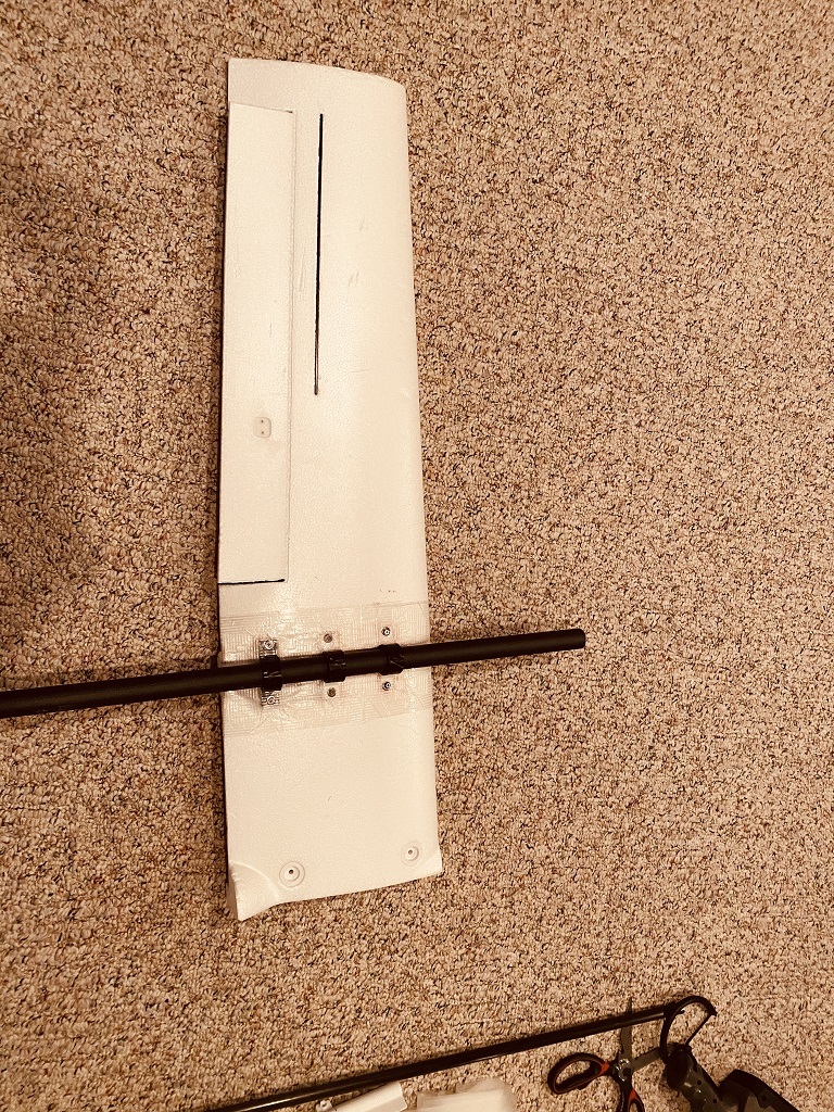
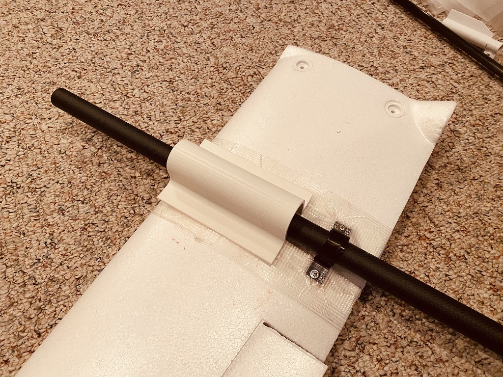
Any suggestions on how to add curve to this part design? See enclosed Solid Works file.
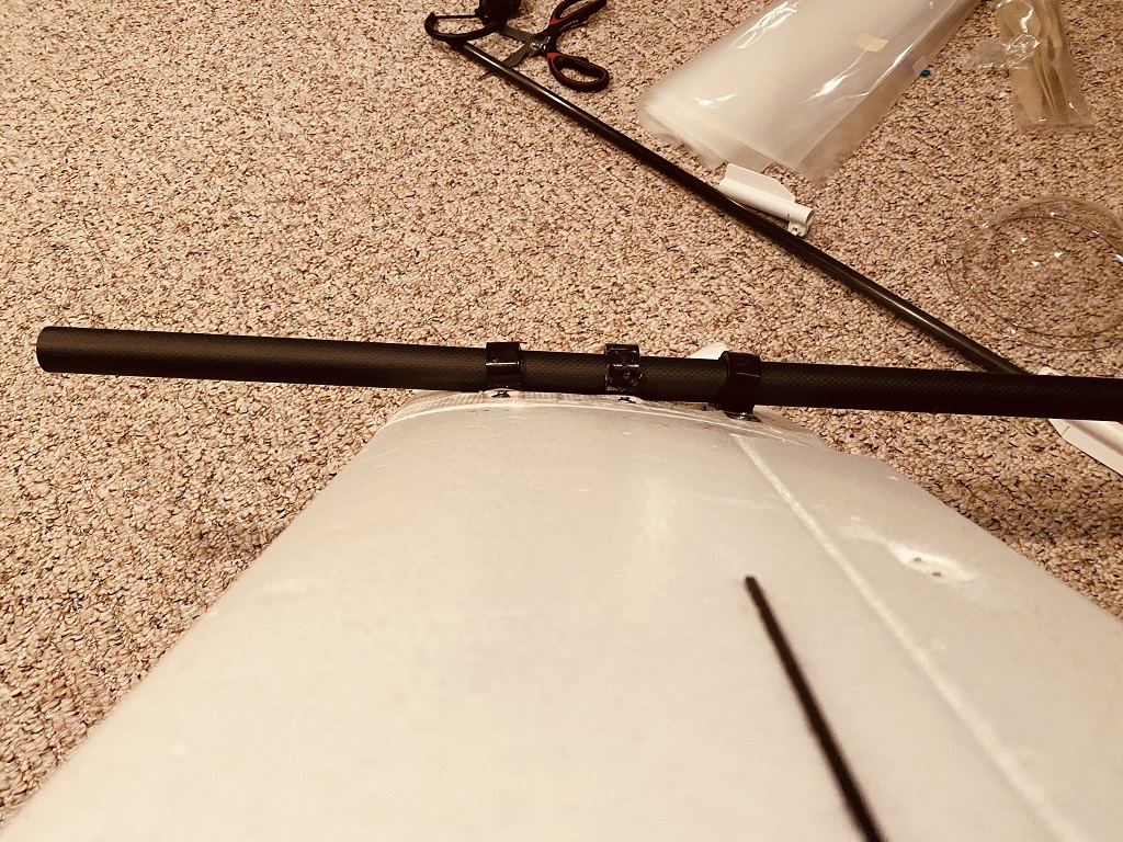
I designed this dom to cover a VTOL Carbon fiber rod which goes on top of a wing. Off course the wing top curves from leading edge to the trailing edge. No clue how to do the curving.
I am going to 3D print it.VTOL.zip (88.5 KB)
I think 9.5" is too long to print. So may be slice it into 2 to 3 small pieces and then add the curve?
You would use a Sweep for that. Stp file attached as an example. You are using an oder version of SW than I so you wouldn’t be able to open a part file.
VTOL Cover (Rev A).zip (8.9 KB)
Thanks Dave. This will help. I have the latest SW. 2019-2020. My friend did the initial design and he has the old version.
I was able to open the file you sent. Let me monkey around with it.
OK, here is the .prt file then so you can see how to do it. Put the wing surface as the path sketch for the swept boss.
VTOL Cover (Rev A).zip (8.9 KB)
Thanks!!! It will be fun to learn how u did it
Hi All.
New guy here… im sorry to ask a bit of a stupid question, but i recently baught a job lot of sensors on ebay and im having trouble working out what the pinouts are on an airspeed sensor.
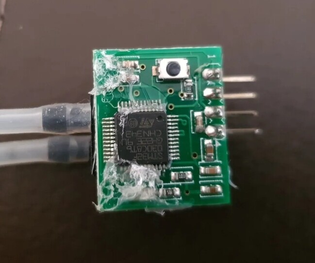
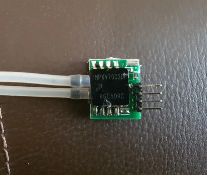
There are literally no labels on the board. I assume its an analogue airspeed sensor, but im not sure ( because it has 4 output pins instead of the 3 usual pins an analogue airspeed sensor has). Is anyone familiar with this board ? If so does anyone know the pinouts? Anyone know of any documentation online?
View of underside of board:
View of top side of board:
Thanks in advance!.
Ged