Acc/Gyro filter is not a Low Pass Filter?

Thanks to the great work of @andyp1per (see Notch filter is not a notch filter?) I was able to log and do FFT analysis on post filtered gyro, and something seemed wrong.

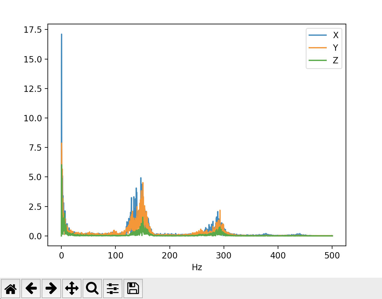
Here’s one FFT post filter with GYRO_FILTER = 80hz (and notch at 144hz, badnwidth 14hz, attenuation 30db) and with “normal” flight speed:

Here’s another with GYRO_FILTER = 100hz (and notch at 147hz, badnwidth 60hz, attenuation 55db), on a fast flight (I zoomed to have same y axis):

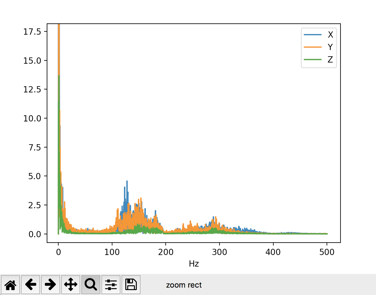
Something seems strange, why I can still see frequencies higher than low pass filter cutoff?
There was a bug in @andyp1per implementation, when applying notch filter the lowpass was ignored, ok, tested again after a quick fix and… nothing changes. I can still see high frequencies in post filtered FFT.

That seemed very strange to me, so I studied the biquad filter implementation and found a couple of bugs in the parameter calculation and in the filter function.

Here’s a quick python sketch with the ardupilot filter algorithm vs standard implementation.
I know this test is on my rewriting of ardupilot C code in python, not a testing on the real C implementation, but I’m planning to run this on a log and I’m also writing a C unit test (but I need some help on how to build it).
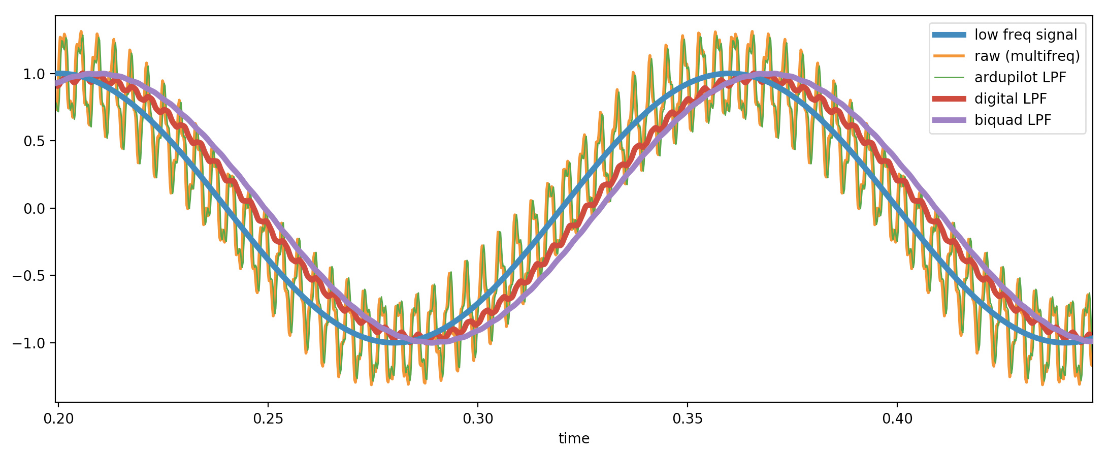
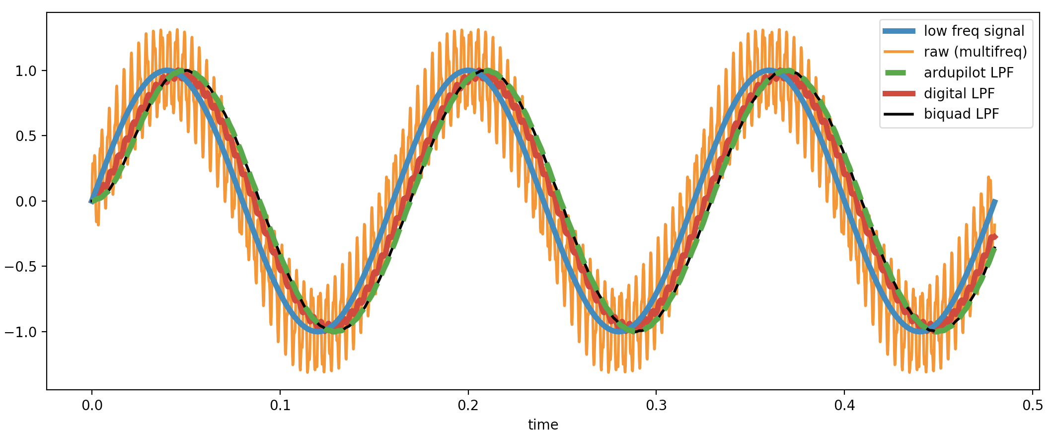
Python test output:


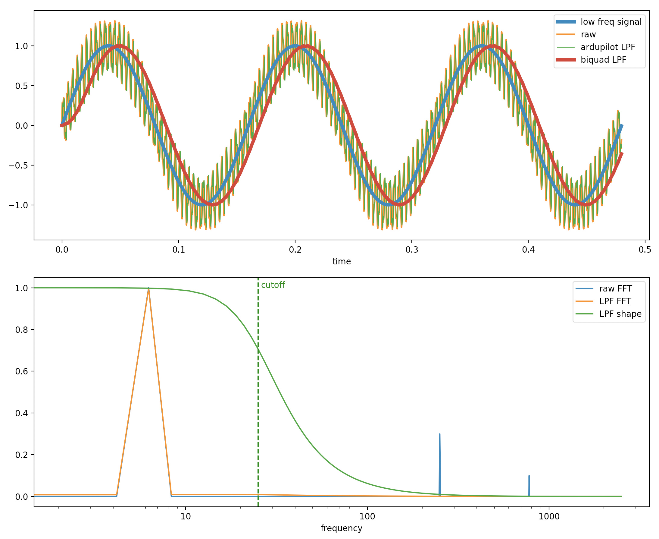
You can see in the top graph that the current implementation (green) is almost the same of the raw signal (yellow), while the standard LPF (red) removes the high frequencies.

It is very surprising to see copter flying well even without a LPF filter on gyro and accelerometer, and that’s why I saw a dramatic change in flight performance when I set up the notch filter.

Here’s the issue on github:

Here’s the pull with the fix:

Tomorrow I’ll test the fix on a real drone and post here the FFT results!

2 Likes

Hey that’s really interesting! I noticed that betaflight doesn’t use a BiQuad at all for it’s gyro lowpass, but PT1 which is the same as the 1p filter in AP. How would that compare in performace to the 2p filter you have created? I know using a 1p decreases latency.

Yes, I was testing also the so called 1p filter, I removed it to have less curves, but here’s the graph with it (in red):

I’ll do some tests on logs, to see the effects on real data.

Here’s the updated python code with digital LPF

So it actually works better than the current biquad implementation?

Wow. I will take a look at this ASAP!

Thank you @Leonardthall

Yes, it seems so.

Here’s what happens on a real log (always using my Python test version of current ardupilot algorithm linked above)

First there’s accel X with FFT and below gyr X with FFT. The FFT graphs are not normalized.

Clearly on the gyro is doing something (but its filtered signal (yellow) is far from the clear biquad(red)) so the current algorithm seems unstable, maybe depending on data or cutoff frequency.

1 Like

A quick look seems to be working fine but I will go over it further tonight.

1 Like

Ok, so I have went over the maths and as far as I can tell your code and the filter in ArduPilot both generate identical filter coefficients.

So I suspect you have made a mistake in your python conversion of the maths.

Hi @Leonardthall thanks for your review, I think the problem is in these 4 lines:

Same as:

x = sample - sample1 * a1 - sample2 *a2
output = x * b0 + sample1 * b1 + sample2 * a2

sample2 = sample1
sample1 = x

Which differs from a classic implementation (e.g. https://www.w3.org/2011/audio/audio-eq-cookbook.html, equation 4):

#sample = current sample to filter
#sample1 = sample at timestep -1 
#sample2 = sample at timestep -2
#output1 = filtered output at timestep -1
#output2 = filtered output at timestep -2

output = b0 * sample + b1 * sample1 + b2 * sample2 - a1 * output1 - a2 * output2

#keep memory of last two samples and outputs for next sample:
sample2 = sample1
sample1 = sample

output2 = output1
output1 = output

By the way I can run the C implementation to double check filtered output.

That is just Direct Form 2 version where you used Direct Form 1.

Thank you, I wasn’t aware of that form, I found a couple of things in my python version that were different from C algorithm, so I updated it (here https://gist.github.com/guglie/8b8242ede6c34539e47cd9a7cdc9421f)

The results of “ardupilot style” filter are still not correct (in my implementation), but to overcome any possible other difference from the C version I’ll test directly the latter to check if there’s still a problem.

:smiley:

Nice!

When I calculate the two filters they result in identical coefficients and work identically in both direct form 1 and 2 cases. So that does not remove the possibility that there is a mistake in the C code but I can’t see any difference between the C and my matlab code.

Thanks for looking over this!!

OK, found another difference in my python version vs C, sorry I didn’t double checked the code because I saw the main difference in the equation direct form I didn’t know.

So now the python test gives same results for both algorithms.

I’m very glad to see that this works properly in Ardupilot, seemed so strange that a very core thing like this was broken.

Now I’m trying to understand why I see the same looking FFT in post filtered logs with or without LPF.

I’m using the python code for this analysis to create a simple python tool to parametrize and apply filters on IMU logs. Do you think it can be useful?

By the way, we have two implementations of biquad filter, one for LPF and one for Notch, I think a good thing would be to use the same DigitalBiquadFilter class for both with different parameters.

Side note, Notch filter biquad filter uses Direct Form 1, that’s another point that confused my analysis

1 Like