Many 4-in-1 ESC’s (perhaps most of them) have signal lines for the flight controller to read voltage and amperage. I believe this is how typical FPV quads get this information - rather than having a dedicated current sensor.
I’ve not looked into doing this with ArduPilot and something like a Cube or Pixhawk - and I’m curious if this can be accomplished - and what the pros and cons might be.
Since this would be a signal input to the flight controller, I expect it would have to be connected to an AUX port - as I’m pretty sure that Main ports cannot accept input signals.
I’ve not done due diligence yet by using google and digging into the wiki. Before I do, I thought it might be worth asking about here.
I took a quick look to see if I could find out if ArduPilot can be configured to read the voltage and amperage data streams from an ESC - I haven’t found anything yet.
Do you know if this can be accomplished? And if it can, how it’s done?
Most 4in1’s will give you voltage and total current thru the ESC via telemetry. A very few will give individual ESC current. If it has 1 shunt resister on the board then total current, if it has 4 shunt resistors then current for each.
The caveat is the current reading only applies to current that ESCs draw and wont cover other accessories or even the flight controller itself.
This is probably OK in most cases, unless you have accessories that draw a significant amount of current.
Most of the 4in1 ESCs have a Telem wire which will provide voltage, temperature, and RPM when using DSHOT. In some isolated cases this also provides current.
The Current wire is an old-style analog current reading using a shunt resistor, I generally ignore this as I’m using the flight controllers power-brick for calibrated voltage and current readings.
There’s usually a V-BAT wire too, which will be the raw battery voltage, used to power the flight controller board in the “stack”. I avoid this too, because I havent used any of those stacks, usually removing this and the unused current wire from the connector.
Some new ESCs using new FETs can report current without using a shunt resistor - these wont be the cheaper BLHELI ESCs. APD F series do this.
With a lot of 4in1 applications the current to the ESC does cover everything as the battery is directly connected and it then supplies the FC with full battery voltage. Many FC’s will take 6-8S directly. Then either ESC telemetry supplies current data or the analog signal can be used. Of course the FC also logs battery voltage. These boards have BEC’s which are supplying accessories.
Yes agreed. I’m just saying that so far I’ve not used any of those stacks, but other typical flight controllers with their own power brick. In that case the vbat wire from the ESC is not used.
Thank you gentlemen, for your responses. Very helpfull.
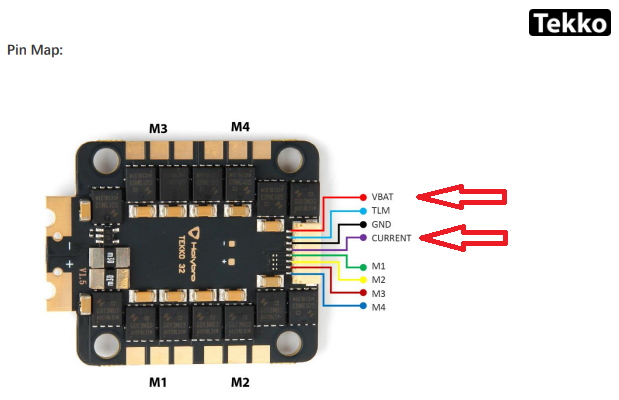
I may not have expressed myself well. Here’s an example, a Holybro Tekko32 F4 ESC:
I want to know if I directly connect these pads for voltage and current to a Cube/Pixhawk flight controller to get voltage and current data.
If so - what ports and parameters are required for ArduPilot to understand this data.
As I understand the comments above, the Vcc pad is for powering a flight controller - not for providing voltage information to the ArduPilot firmware.
I’m not so sure about the Current pad. My guess is that this provides a voltage signal that varies with current - similar to how the Mini Power Brick or Mauch current-sensor/BEC provides this information.
If this is true, then I’m guessing the ESC Current pad needs to be connected to Pin-3 of the Power-1 port on the autopilot.
Pin-4 of the Power-1 port is for voltage sensing - perhaps the Vcc pad on the ESC could be connected to that.
If this is the way to make these connections, then adjustments would be made in a similar way to calibrating an “other” battery monitor.
I already told you. If you use FETtec ESCs you do not need connect any extra pads and you get all the information you want in digital format. The configuration is explained in the links I posted
You would likely damage a Cube by doing that. That input is 3.3V max and the Vbat pin on the ESC is direct battery voltage. That output is typically used to power an FC that takes direct battery voltage. There are many boards with that capability a Cube is not one of them.
You are correct about the current pin. That is a voltage equivalent from the ESC shunt resistor similar to how non-Hall power modules do it.
I have used ESC telemetry on these ESCs (slightly different model) to get current and voltage to an mRo.
One heads up - the data output is very noisy (in terms of measurements not quality of link) and not as reliable as a dedicated power monitor. It was enough for me to rely on for battery failsafes tho.
I don’t know much about FETTEC ESC’s - but I gather that their appeal has to do with the ability to do sinusoidal control.
I’ve been sticking with BLHeli_32 firmware for this reason - they introduced Sinusoidal as an option over Trapezoidal about a year ago.
I probably won’t go to to a FOC ESC until I need to go over 6S. There are BLHeli_32 ESC that go up to 65A - which is plenty - but I haven’t come across one that is over 6S.
I haven’t found a way to measure the efficiency gain of sinusoidal over trapezoidal, so I’m just taking it on faith for now.
Connect the TLM telemetry output from the ESC to the serial RX of your flight-controller. The signal-pins S1, S2, S3, S4 from the ESC are used to receive the commands from the flight-controller, so the serial TX from the flight-controller must be connected to every signal-input in parallel. Connect the GND from the FC to the GND on the ESC.
Only three point-to-point wires (but one of then is connected to simultaneously to S1, S2, S3, S4)
When used with typical FPV flight controllers, the “VBAT” line is used to both power the flight controller board and for the flight controller board to sense the battery voltage. The “current” line is actually a voltage that is proportional to the current through the ESC shunt resistor. The TLM line on a BLHeli_32 ESC can provide telemetry including the voltage, but likely won’t include the current since that’s separate.
If you use a standard Pixhawk power module (like a Holybro PM02D to power a Pixhawk6X) then you can get your current/voltage/regulated-power-for-the-FC from the power module and you don’t need to connect the VBAT/TLM/CURRENT lines from the ESC at all.
On a few of my smaller quads, I use the CubePilot Mini Pilot Brick for current sensing. For the rest, I use Mauch current sensors.
When I started with BLHeli_32 4-in-1 esc’s, I used FFT for the dynamic notch filter. I wanted to use RPM for the notch filter. I’ve implemented bi-directional d-shot, so I use that as my rpm source input.