Hello Chris & thank you for all the info regarding the Wild Thumper. After considering all of the advice given to me in here, I know that I’m far from knowledgable but all your advice has been beneficial. I wanted your opinion in the potential of hooking up a Pixhawk to the following rc car.
I’ve been told on the standard battery it’s supplied with it has a runtime of 2 hours which is enough for me.
It also has the ability to take a payload of 3KG which is more than enough for what I want for my project.
Just not sure if the Pixhawk can be added and if the controller is also suitable. Please let me know your thoughts when you have time. Many thanks

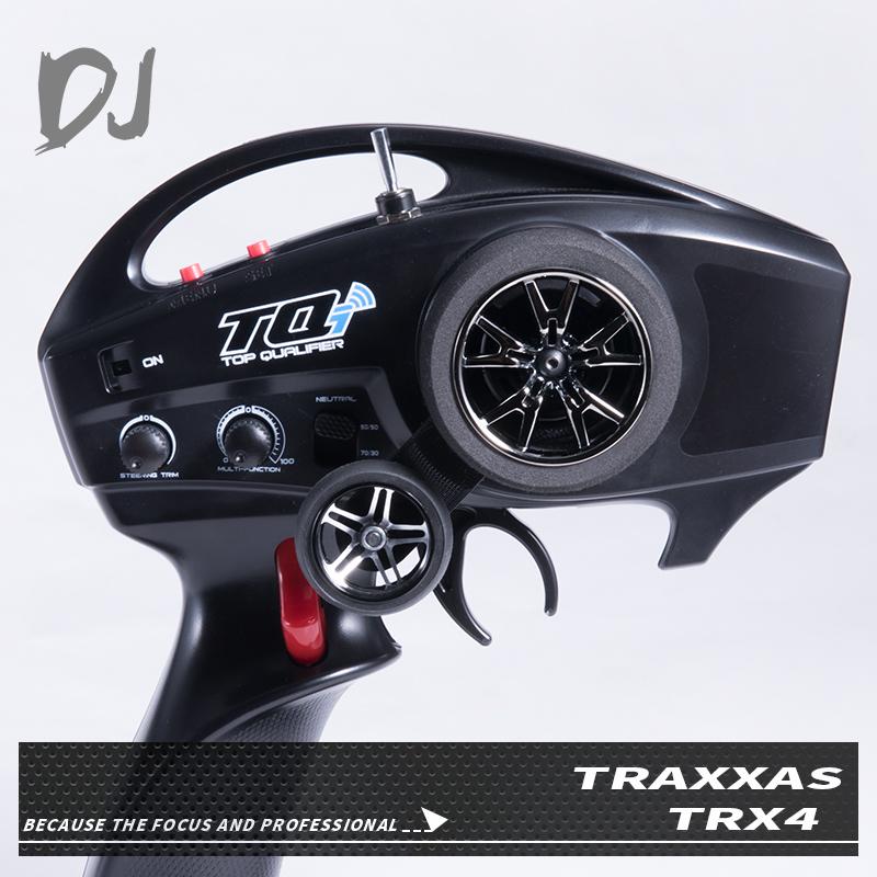
I’d say if your Pixhawk can directly control an R/C servo motor then it can control this R/C truck. Your controller needs to output the normal PWM signal that a servo is looking for. I’m pretty sure thisis the case. I notice this model truck has a “crawl mode” which meads it should be controlable at very low speeds. That is good. Robot cars need to go slow.
Only thing is with this rover that I’m thinking of modding is will it be possible for the to spin on the spot? Like the Wild Thumper it’s wheel power is split to 3 wheels on the left and 3 on the right which can then help the rover turn in 360° Or 180° on the spot and then go forward.
I also looked at the Aion Robotics R1 Rover which is an impressive piece of kit. But length is only 18 inches! Even a 1/10 scale rover is 24 inches which I still think is pretty small but 18 inches is just tiny!
Buying all the parts and creating my own rover will cost me over £1,000. The R1 is also around £1,000 and then import tax to add aslo, will save me allot of headache to buy something ready made. I’m just in a predicament about what I should do now
Buying parts and building from scratch can actualy be very inexpensive if you use repurposed and salvaged parts. For example the gear-moters used to roll up and down the windows in cars. The moters can be taken from junked cars and fitted to a 3D printed chassis. Old inkjet and lazer printers have many usful motion control parts in them. But designing anf building this way is a LOT of work
That’s the thing I don’t have the knowledge for such a build. Plus I’m happy to spend the money to save me the headache. The R1 is within my budget but way too small, the Wild Thumper is also within my budget. The Traxxas TRX 4 also within my budget.
Like I mentioned with the TRX 4 rover would it be possible to make the wheels on the left side reverse and the wheels on the right go forward at the same time to create a turn on the spot. Similar to the Wild
Thumper
Of course not. It only has one motor driving thru differentials. You need independent motors left to right under skid steer control to do that.
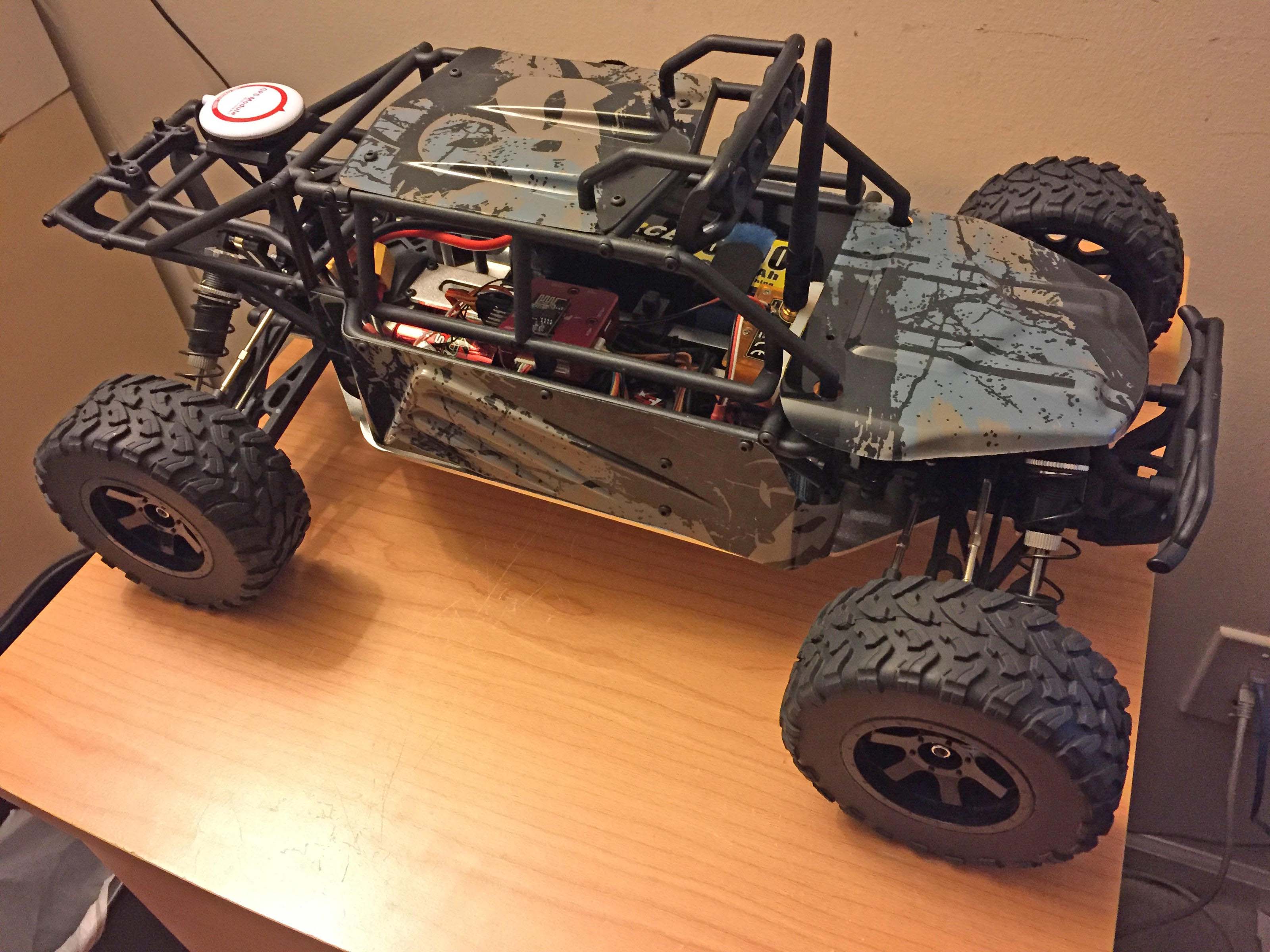
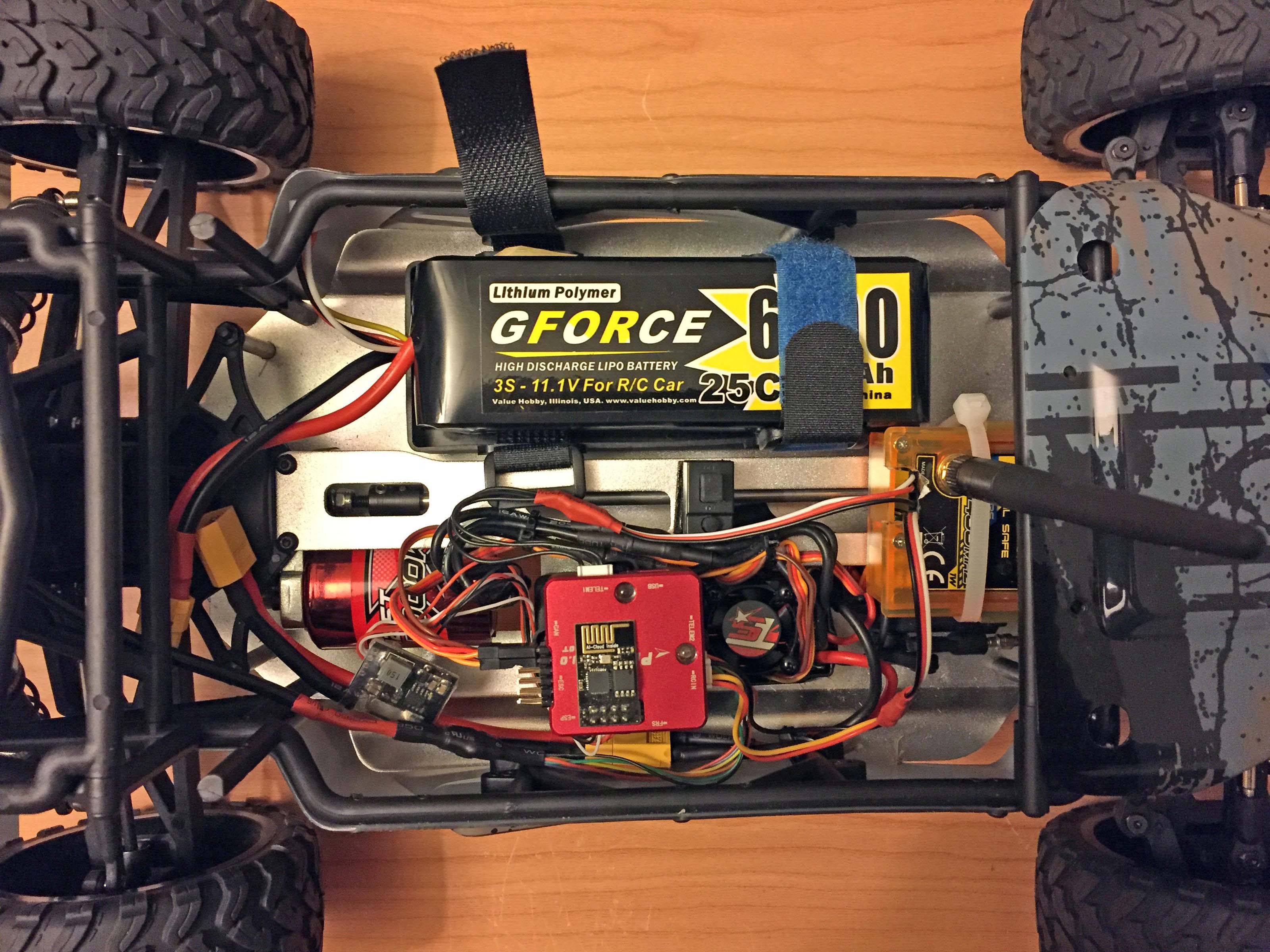
And as far as controlling it with a Pixhawk, sure it will work. Worst case you may have to use your own Reciever and Transmitter depending on what the stock Rx produces for control signals. Pixhawk only accepts Sbus/PPM. Attached are a couple photos of my Rover, which won’t suit your needs, built on a cheap Hobbyking 4wd truck to give you an idea of what’s required. The FC is a PixRacer.
1 Like
Love the look of your rover!! I’ve finally ordered a 1/10 rc crawler and I’m looking to learn with it. Thought I’d go cheap and cheerful before blowing up a Traxxas TRX-4.
Here’s the one I’ve purchased:
Another question I have is regarding the APM Power Module:

Max input voltage: 30V
-Max current sensing: 90A
-Size:25219mm
-Net weight:25g
-Voltage and current measurement configured for 5V ADC
-Switching regulator outputs 5.3V and 3A max
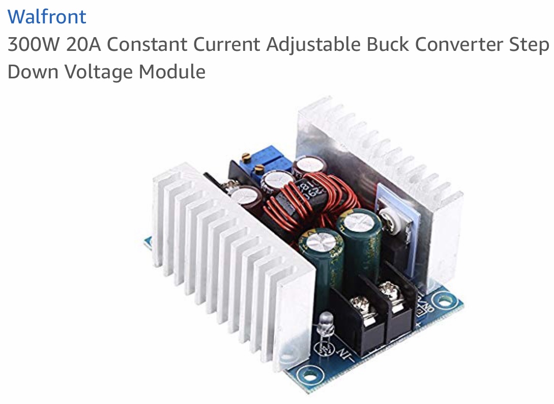
What is actually required to input into the power module for it to power the apm? Does it need exactly 30V & 90A or can the input into the module itself be much less than this? I’m assuming that the minimum amount that’s feasible to make it work is 5.3V and 3A. Or am I wrong with this assumption? Sorry if this is a dumb question but I was thinking to add a bigger power supply & step down regulator. Like this:
300W 20A Constant Current Adjustable Buck Converter Step Down Voltage Module https://www.amazon.co.uk/dp/B074FW4KJ8/ref=cm_sw_r_cp_api_i_q-7mCb2M256VT
Then adjust the output end to 5.3V and 3A and then I could add a bigger power supply on the input end which the current power module can’t really handle
Good plan with a cheaper vehicle to gain some experience.
You are wrong with that assumption. Are you reading any of the material some of us have suggested? You don’t need a buck converter, simply connect a 2S battery* to the power module and connect the power module to the Flight Controller. The power module serves 2 functions. It supply’s 5.3V to the the Flight Controller to power it and peripheral devices (Rx, GPS, telemetry radios, etc) and provides a scaled output for battery voltage and current. That’s it. It does not power anything else. It’s inline with the lead between the battery and the ESC.
http://ardupilot.org/copter/docs/common-3dr-power-module.html
*Because that’s what the motors and ESC on that vehicle are rated for.
1 Like
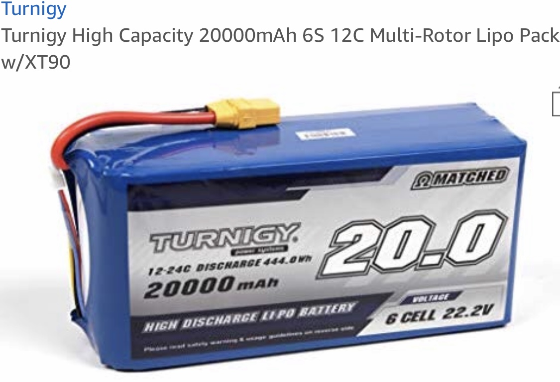
Here’s the thing I’d like to connect more than a 2S lipo. I currently have a 4S connected to the power module.
What would I need to do to connect let’s say a 6S 20,000 mAh lipo? Would I still be able to run through the power module or would I need the buck converter to achieve this?
You have already been given the answer to what voltage that Power module can accept and it’s right in the spec.
Here’s the thing. Good luck with your Rover.
Thank you for your time & advice. Sorry if my lack of understanding has caused you headache. It’s genuine misunderstanding on my behalf. I will get it eventually…I hope 
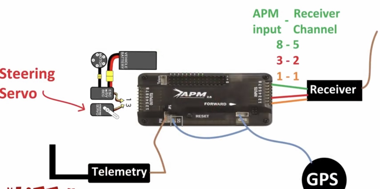
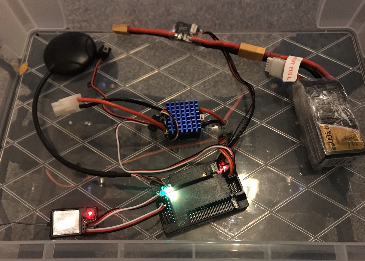
Hi Chris. I’ve decided to build from scratch and so far so good. I have purchased a rover & have successfully added the APM 2.8. I have wired the components as follows:
Because the transmitter is only a 2 channel I have now ordered the Flysky FS i6 for more channels to also provide the option to switch to auto mode once I setup a flight plan on Mission Planner.
What I’ve noticed is that it says on many tutorials that you can’t power servo’s and ESC’s through the APM but oddly enough I’m able to do this. Is this normal?
When I use power from the lipo battery directly into the ESC which then powers the APM it doesn’t function as well as when I power everything via the APM “which like I said you shouldn’t do”
I’m wondering why this is happening?
Any advice would be appreciated. Thanks in advance
If your ESC has an integrated BEC it will power the APM and any servo or other devices connected to the servorail. If you power the APM with a power module, there will be no power at the servorail from it and you will need an additional BEC to power the servorail.
When powered through the apm power module everything works fine, the apm and rover both have power and works.
When powered through the ESC and connect the battery to it nothing seems to work properly.
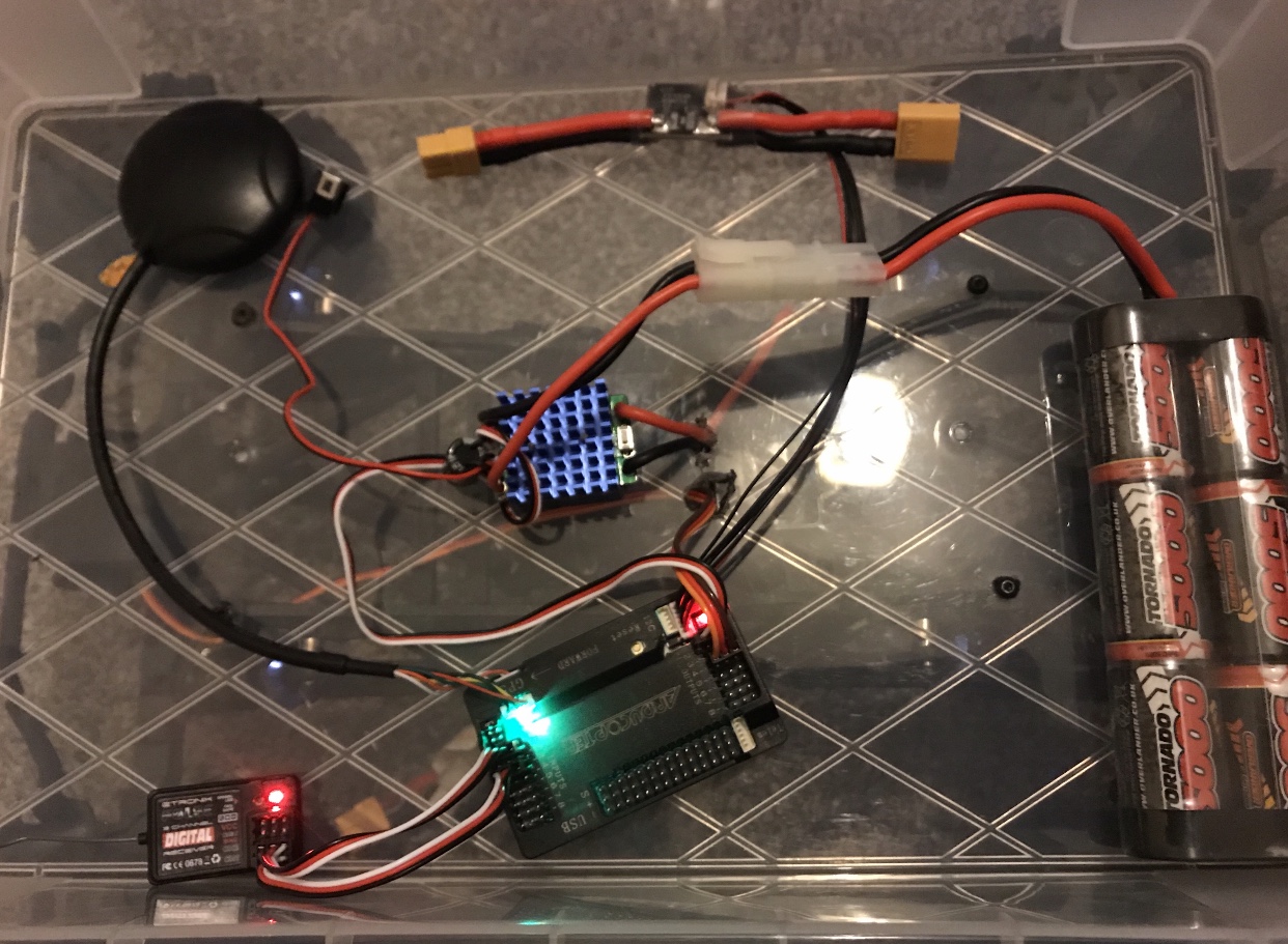
So I’m guessing that this ESC doesn’t have an integrated BEC.
I don’t know why "they"say you can’t power a servo from the APM board. They might be right that it is a bad idea even if initial tests show it can work. I don’t know.
One good reason NOT to is the current the servo needs might be more than the board can safely provide. Tests done with a bare servo are not realistic because the motor is unloaded and not needing much current.
In short, maybe it works on the lab bench when the robot is on blocks with wheels in the air but fails (smokes) when driven outdoors. You just have to look at the specs.
If a separate servo motor power supply is needed, all you need is to buy a DC/DC step down power supply that is rated for about 2X you motor’s worst case. You can find these on eBay.
I’ve seen theee stepwdown converters and was thinking of buying this one:
Basically my thought was to have 1 Lipo to power everything rather than havin 2-3 lipos.
In the manual it says the following specs for the ESC:

The step down module has an output of 20 amps but they recommend going up to 15 amp Max. Not sure if going through the module would be enough to supply a
consistent amount of power to the ESC & Sevrvo?
So I was thinking of buying one of these:
Then having a parallel output from the lipo for 2 devices. 2 step down modules setup before each device. Would this be a realistic option to increase drivetime & keep the lipo battery’s to a minimum and just use 1?