Hi all, just a quick one… what’s the latest version of th SIYI FPV app??
Thanks !
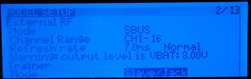
@Risto Report about SBUS Out with X9D on External RF Modul Connector.
At first it worked with a Interface IC 74C902 to adapt the Voltage Level.
But the SBus Out of the Taranis is not stable because the Output Driver probablyis not fast enoughe.
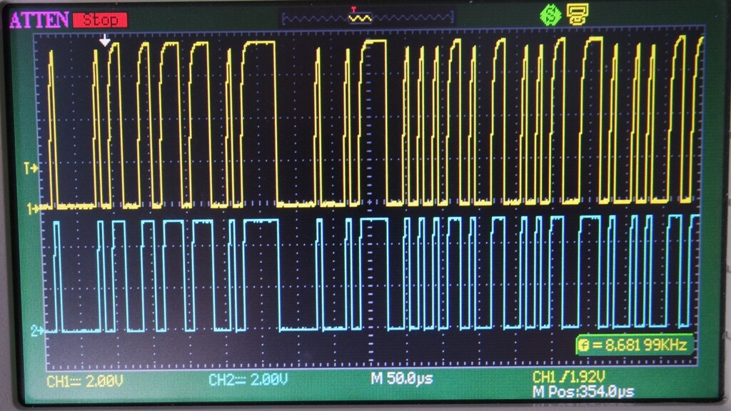
Sometime a single Bit achieve half the logic level (without charge) until it drops to zero. Sometime nearly the max. Voltage as in the pic below. And even the signals are stabilized with the the Interface Chip (blue) HM30 does then not recognize the SBUS Input. And sometime it does. Not verry trustworthy. ![]()
I think I will stay with 8 PPM Channels, only.
S.BUS is nothing more than inverted UART at 100.000 baud 8E2.
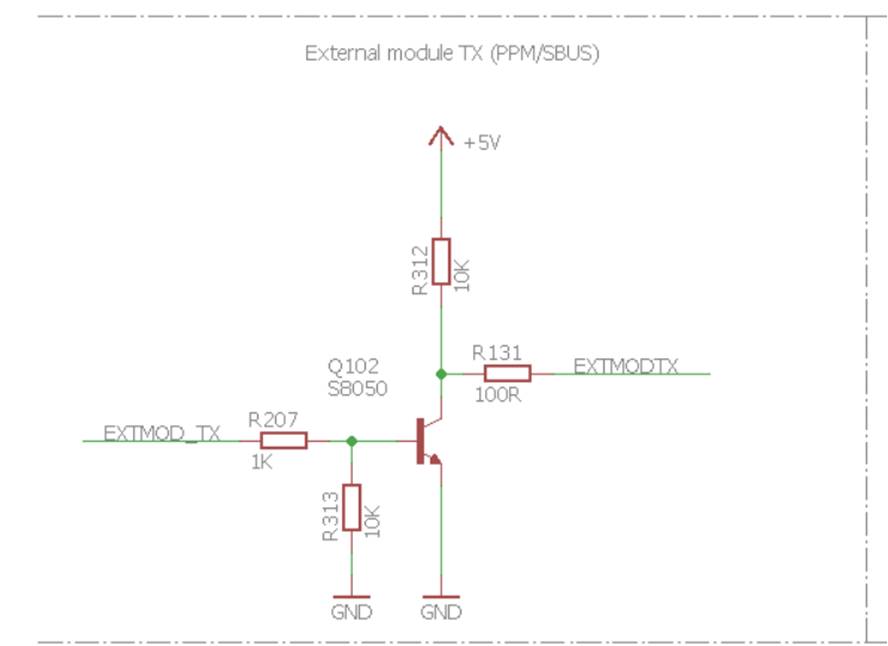
I do not have the schematic of X9D to check, but on TX16S the PPM/S.BUS JR-Bay pin has internally open-collector output stage (see Sec. 2.11: Blog #17: RadioMaster TX16S schematic diagram - RC Groups ). Nevertheless, PPM/S.BUS output works just fine with it for me.
The shape of signal in your scope images may be caused by the low sampling frequency of that scope on that timescale. Try with a shorter time span/higher zoomed in view to see if the signal shape really is as rounded, as shown by this zoomed out view.
Do you have schematic of your voltage converter? Assuming X9D also has no push-pull output on that pin, maybe your voltage converter has a pull-up or pull-down resistor or a filter capacitor on the signal line that interferes.
Thanks for answering.
The scope has 60 MHz and digital storage.
The blue signal is the out of the Non inverting Driver and shows rectangular signal.
There must be a pull up inside Taranis. When I connected a 20 kOhm Resistor to ground, the out droped from 8 to 6 V. The SBUS Signal looks bad even without any load.
Attached the Datasheet of my Driver. The supply voltage of it comes from 5V at the RC Out of HM30.
74C902N_Fairchild.pdf (68.2 KB)
Did you connect 74C902N directly to Taranis JR-Bay? See in datasheet under max ratings: Voltage at Any Pin −0.3V to VCC + 0.3V. If your chip supply is at 5V, then the input signal should NOT exceed 5.3V.
Yes, you are right. I have probably damaged the Taranis Out.
The Driver 74C902N ist still working.
I assumed, there is a internal resistor like in RadioMaster which limits the current from 8 to 5 V.
What Transmitter do you own and how did you realize the connection?
Edit: Just read you own the RadioMaster. I’v seen in Bangood there are different Models.
Witch one can you recommend, I would like to buy one.
Are you sure that you have damaged the output stage of your X9D, as typically you can even short it and they will survive.
But, if you are looking for a new radio, have a look at TX16S mkII. Base model is fine, but if you want more solid metal gimbals, go with AG01 or get the base model and upgrade to FlySky HZCZ gimbals.
P.S. No resistor in TX16S in the above circuit does the voltage minimization - the reason, why TX16S PPM/S.BUS pin has 5V max is because of the supply rail of PPM/S.BUS being internally at 5V.
Thanks for the quick response.
I assume to damaged the Out of the Taranis due to the strange behavior.
For the design I also thought the out is shortcircuit proof.
- The SBUS Signal as designed with the Driver 9 is no more recognized in HM30
( in the Display, SBUS x) - At first it worked, could even calibrate the RC Signals with MissionPlanner.
- A next time, no more Signal and when checking with the Scope, the smaller Impulses reached max. the half of the others due to the slow flank rise.
- After charging the battery of the TX (from 7.6V to 8.2) , it worked again.
- Next day, I wanted to check, how long it lasts until the Voltage is no longer sufficient.
And it didn’t even work with 8.2 V but the signal had the level of the pic posted above. Means the smller Impuls reached just the normal level.
You are right with your question. When I change the Type of the ext. Modul to PPM (max.8) the
Signal on the Scope shows a perfect rectangular Image.
With the limiting Resistor I meant the Taranis, like in your diagram of the TX16S the 100 or 10k Resistor.
I found this TX, but no idea if ELRS or 4 in 1. (ELRS seems to be complicated)
100R is current limiting (to minimize EMF and signal ringing), 10k is just a pull-up.
If you fly planes, or in general use more than 4 high-fidelity proportional channels, 4-in-1 is IMHO presently better choice. The priority of ELRS development is super fast update rate, low latency and long range.
On the other hand, if you use HM30 as your radio+MAVLink+video link, then you do not care much about internal RF module type, as the internal RF module in the radio will be likely turned off anyway.
Thanks for helping. Not only yes or no, perfect explained why.
So I will order it.
Can I load the models with OpenTX directly after setup of the new Radio?
Did you connect HM30 directly to the ext.Modul Port for SBUS (no Voltage Difference)?
I’m now a little bit scared ![]()
TX16S mkII comes with EdgeTX. Best you check if it comes with the latest EdgeTX release version, if not update to that first (presently 2.7.0). You can use EdgeTX Companion to import OpenTX models, but there are some differences, especially if you come from black-and-white radio and go to color radio, so best you double check all the settings, before going to fly.
Yes, I directly wired the GND and PPM/S.BUS lines from JR-micro bay to HM30 ground unit.
I understand you recommend to change from OpenTX to EdgeTX ?
This helps to stay mentally fresh. ![]()
The latest one is the .300 version existing in the link
https://drive.google.com/drive/folders/1r0G1I0JS-_3g5pW_u6Hnvsn3eMuc90O3?usp=sharing
1 Like
In this .ZIP File is inclouded a second .apk with the name SIYI_TX…
What is this App for?
SIYI TX is for other models like MK15 for configuration, it does not work with HM30 as HM30 already have all necessary configuration in the built-in screen
Hello guys, I purchased a HM30 SYSTEM (FLYMORE) and I have some questions to be answered.
-
I would like to do dual link rc relay. I noticed " that it is only possible to do the dual link and rc relay if I buy the dual link product, but if I buy another ground unit is it possible for me to do the rc relay and dual link ?
-
I noticed in the manual that the minimum distance between the antennas of the air unit is 5cm. If I increase the distance between the antennas is better or is there any ideal measurement between the antennas?
-
I will use the system on a reconnaissance platform, I will need a zoom camera, somebody have already carried out tests with cameras of this type?
-
When I link the ground unit with the air unit, the ground unit LED is solid blue and the air unit is flashing blue quickly, the link quality on the display shows 100% (In the manual it says that the ground unit LED and the air unit LED should be solid blue).
-
I have a radio with 7 channels but two of them i would like to use as pwm to pan/tilt the gimbal. how to make?
1 - Elevon right (S.BUS)
2 - Elevons Left (S.BUS)
3 - Trottle (S.BUS)
4 - (S.BUS)
5 - Flight mode (S.BUS)
6 - Pan (PWM)
7 - Tilt (PWM)
thanks for listening
Regarding your last point. S.BUS would be 16 proportional channels plus 2 digital channels. Are you planning to use a flight controller anyhow? If so, these can convert S.BUS to PWM (e.g. to control PWM capable gimbal or std. servos). In case you do not want to use a flight controller, you can use a S.BUS to PWM converter, e.g. from RMILEC that you attach to HM30 air unit S.BUS out port.
Brilliant!!!
Easy solution and already solved, thank you very much!!!
Regarding my previous question about “AIR UNIT connected but no video from camera”. After few attempt of setting up of the camera address it started to work. I was happy for two days. And today…
Fan is not spinning on power conenction, fast RED-GREEN-YELLOW blinking.
Air unit is not connecting to Groud. If to try bind again - no reaction. Air unit doesn’t change led indication on bind button press.
Tried to connect / disconnect fan and camera - nothing.
I didn’t made any attempts to connect AIR unit fo FC yet. Only Ground Unit and Air with Camera.
Something is wrong with this Air Unit from the start. And this will be second already ![]() First had binding issue.
First had binding issue.
Hi Marcos,
I’ve already replied your email and I’ll post the answers here again.
- The air unit antenna distance should not be less than 5 cm. This is the only limit to distance.
- Dual RC and RC relay are ready in the HM30 Dual Link Combo.
- Sorry, the air unit status indicator is green in normal situation. The ground unit indicator is blue. I’ll revise the manual.
Best regards,
Frank