Documenting this will be an ongoing project. I will add to it whenever I have time. PLEASE feel free to contribute! The more insight the better! I know there are a ton of people out there that have tried and just given up when trying to make an AT and get it to work.
After fighting for weeks to get AT to work, I finally got it. Since there is limited detailed documentation on AT, I figured I would start putting together a step by step guide to what worked for me, and some key items that are critical for it to function properly that may not be immediately apparent to those of us with limited experience with Ardu/PX4. I know just about nothing about any of this and really learned and figured it out through this project and forum. Unfortunately, most of the others who responded to any of my posts for help, seemed to have the same issues, thus why I am doing this.
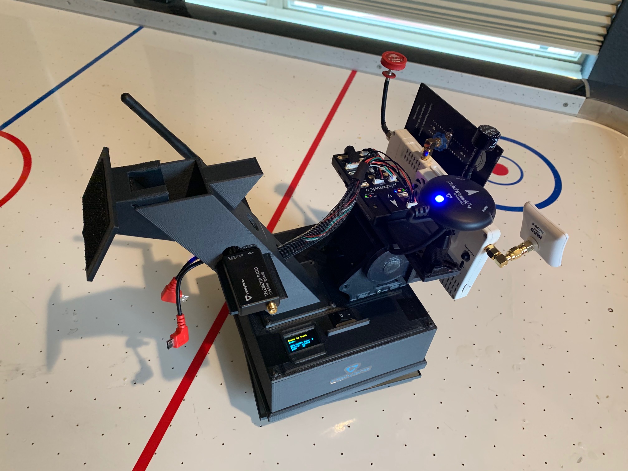
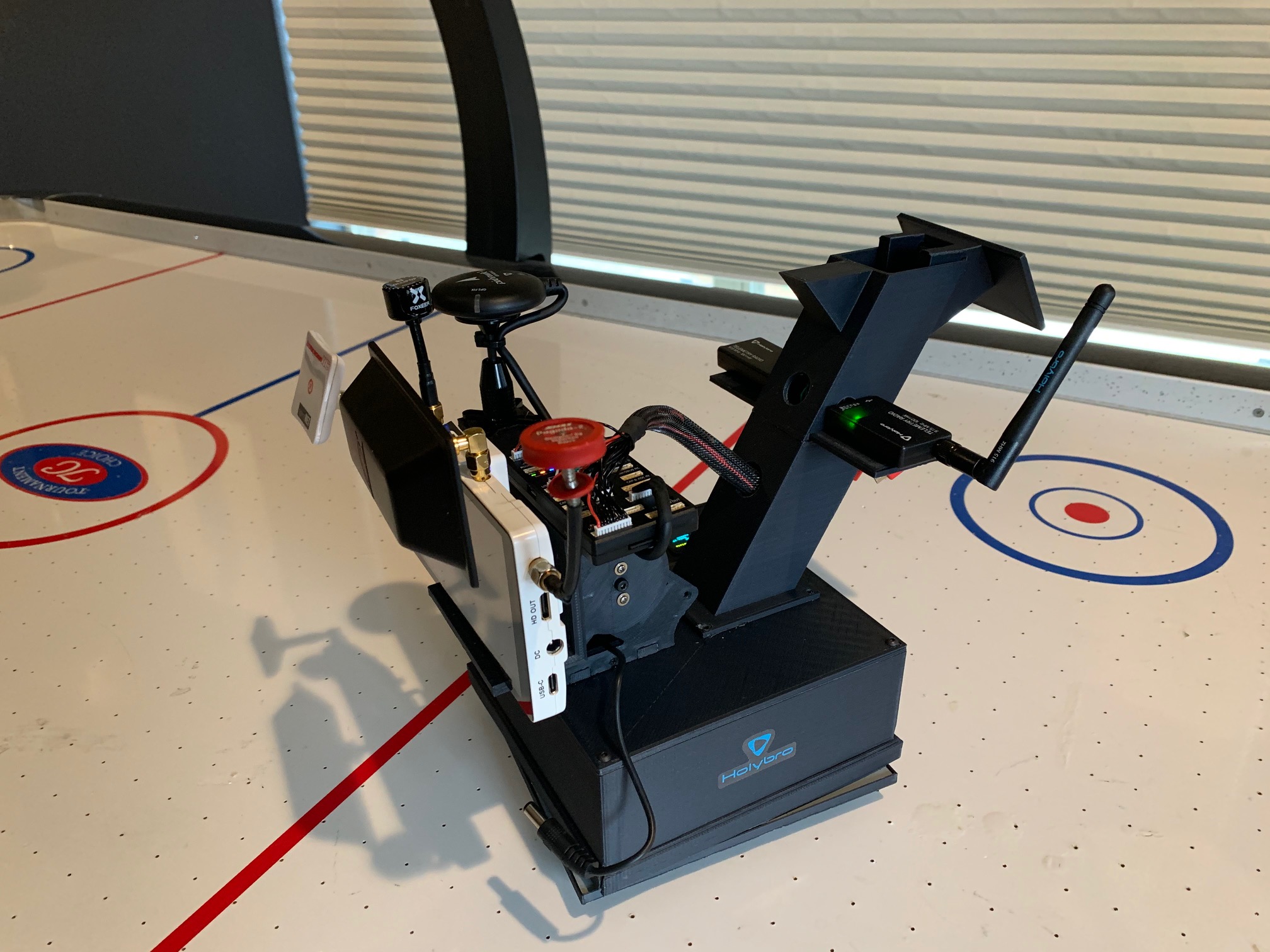
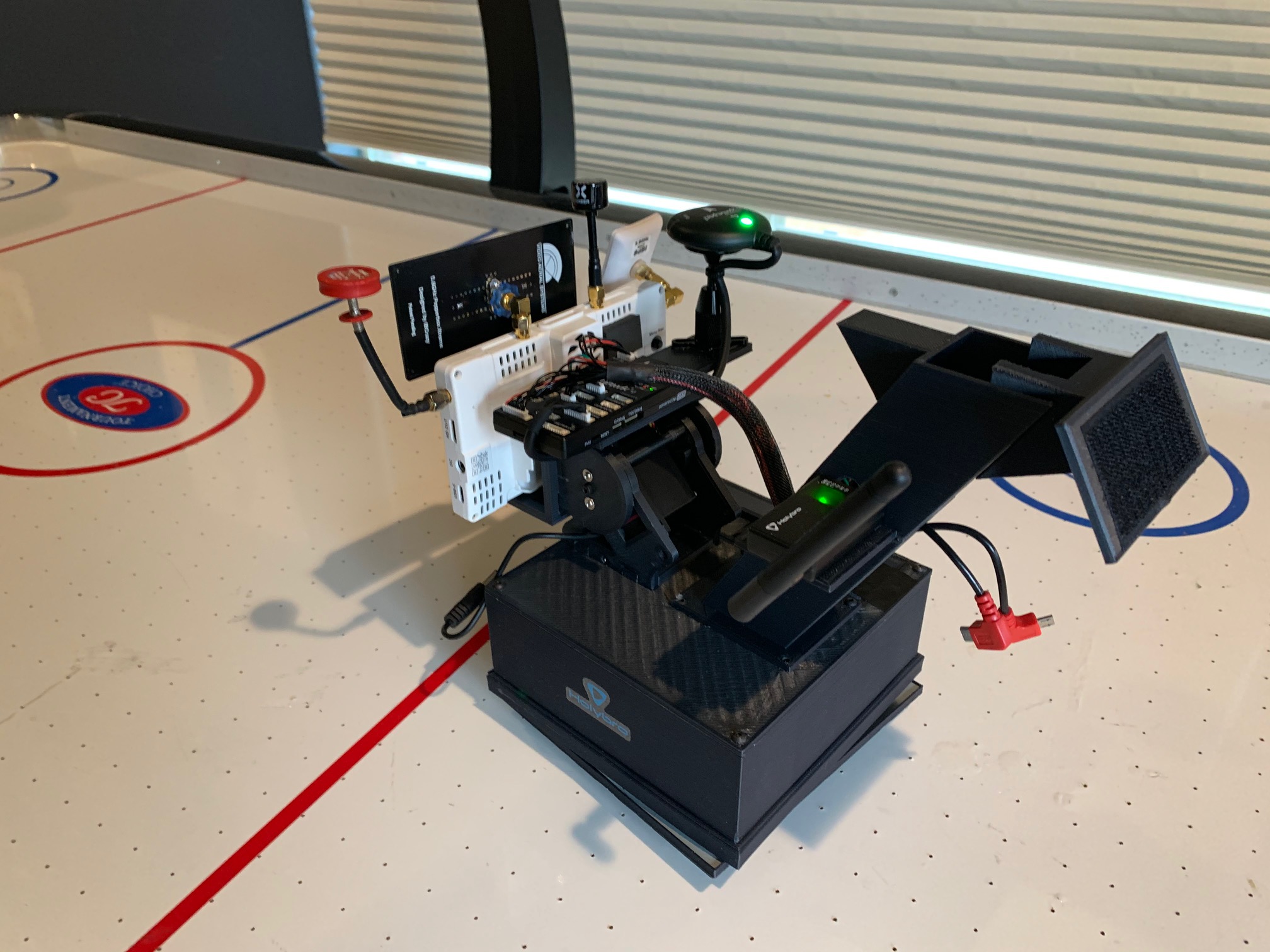
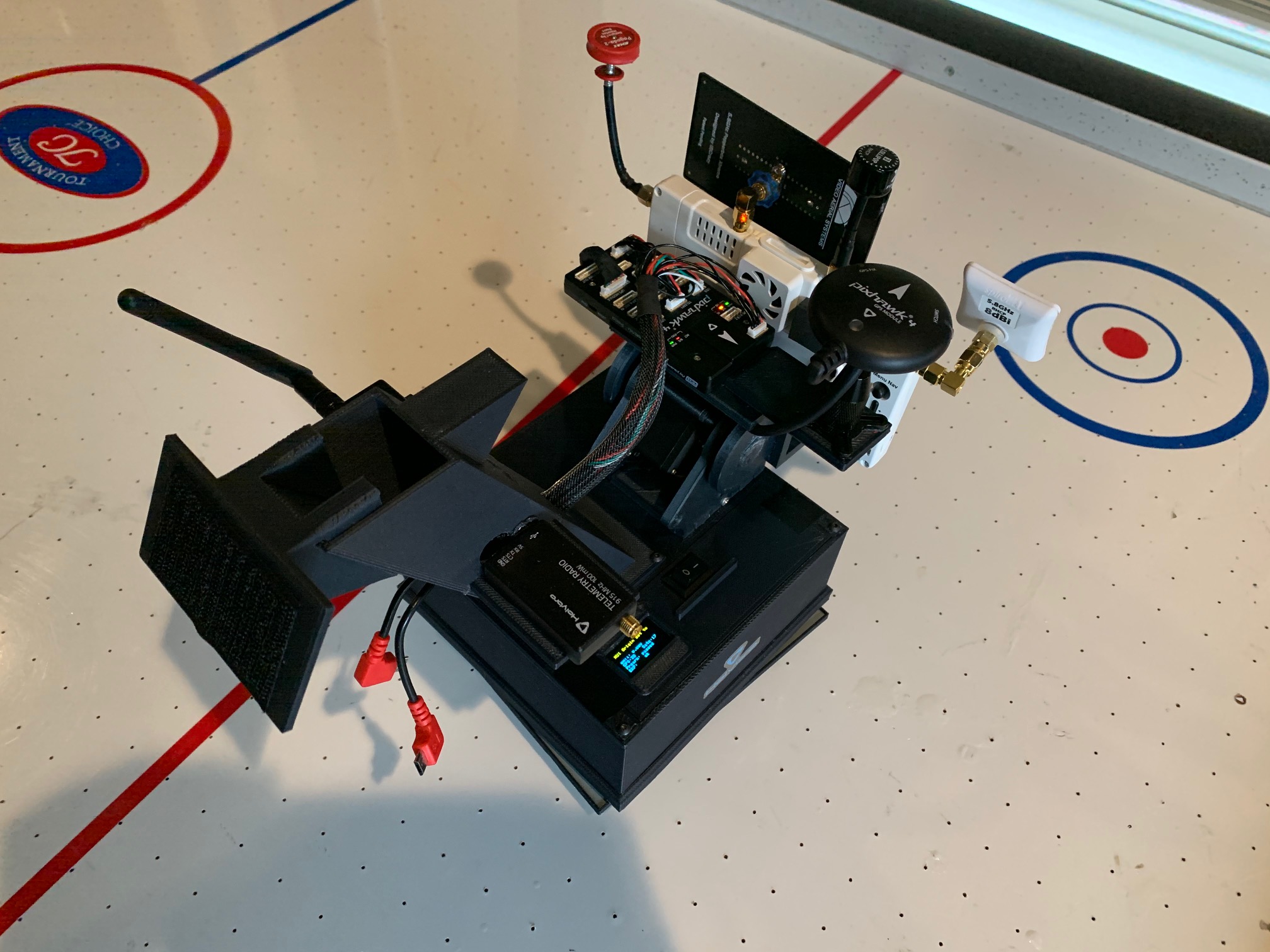
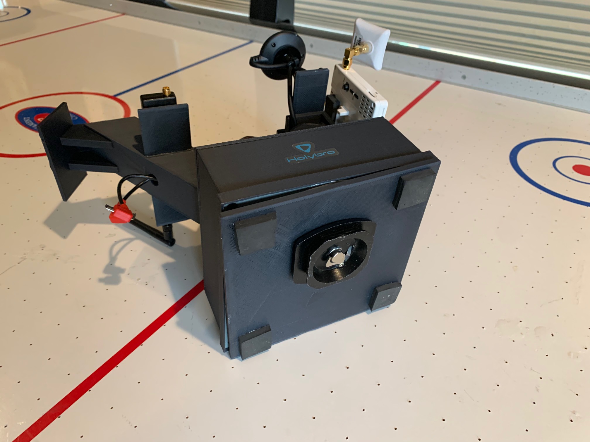
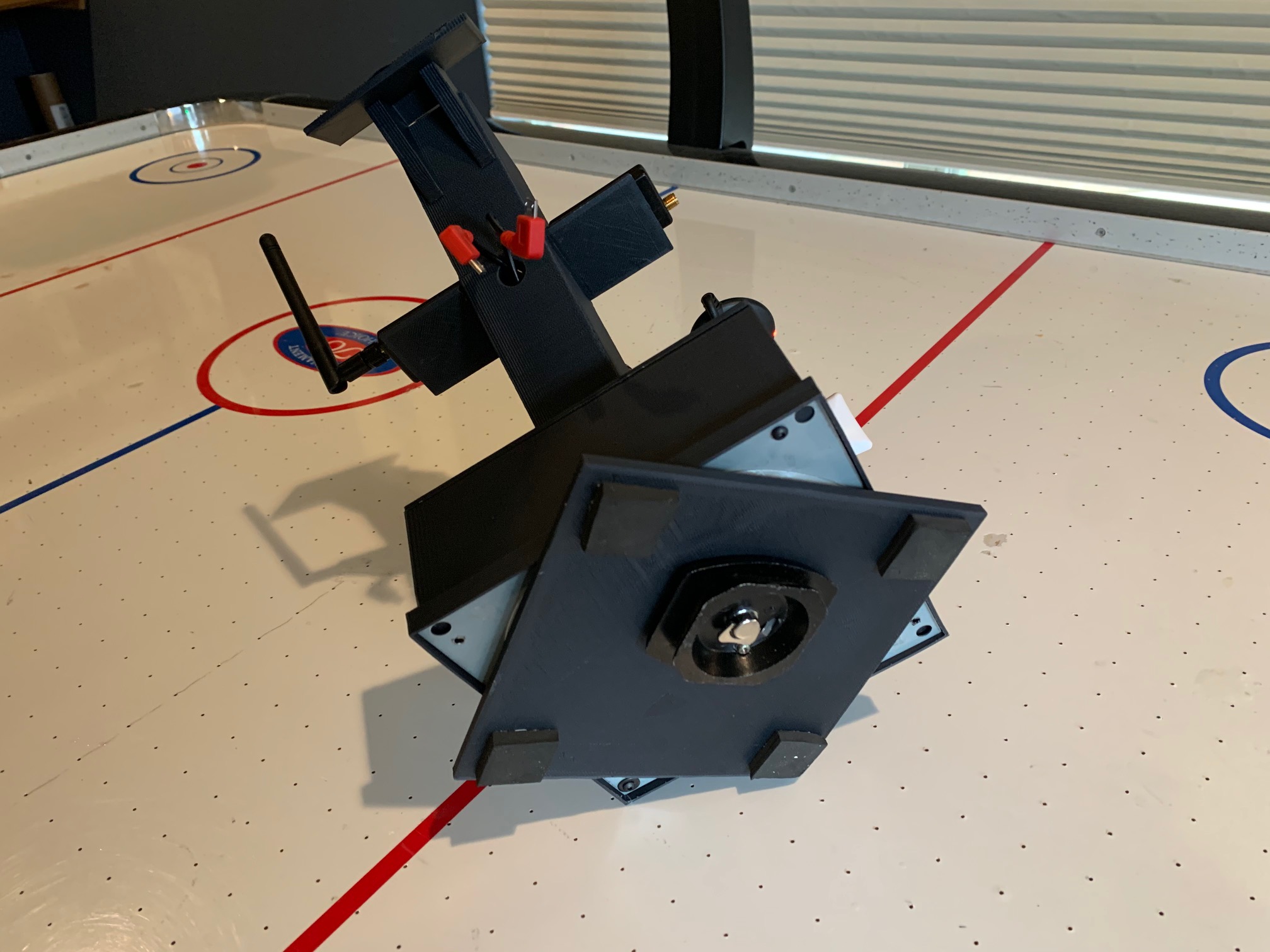
Here is a link to my GitHub with the .stl files, parts list, and parameters of the tracker I designed and built with a 3D printer.
All of my documentation is based on my setup using the following.
-MP 1.3.7
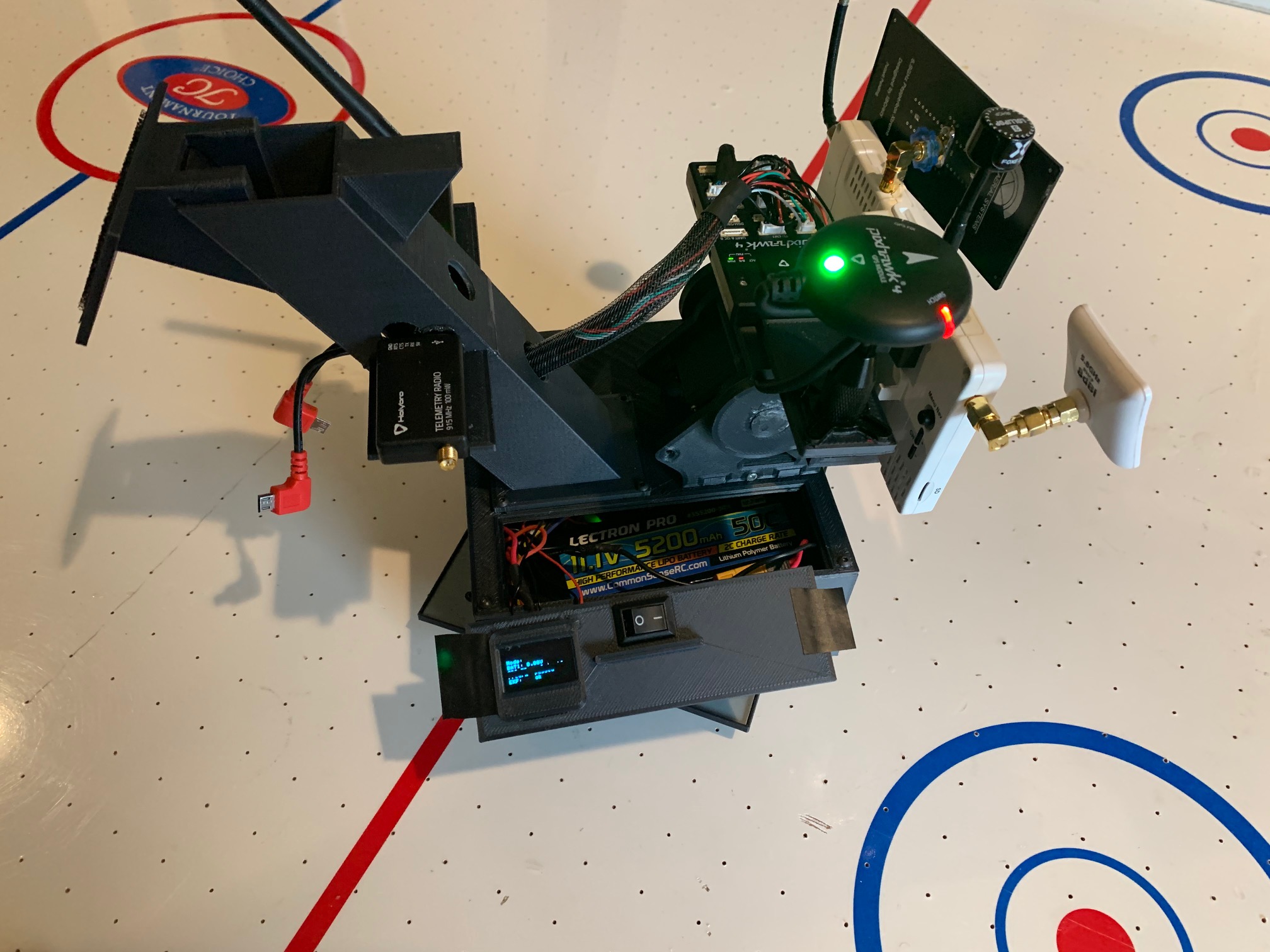
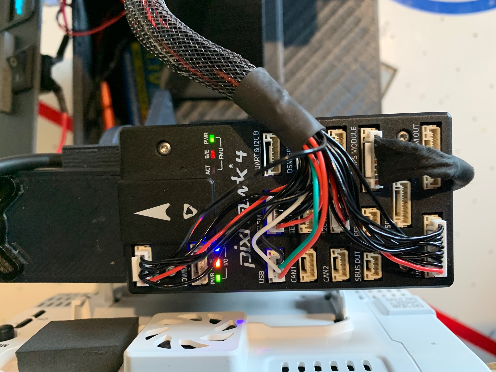
-Holybro Pixhawk 4 board with GPS
-AT 1.1 Stable Firmware on Windows
-Custom designed Antenna Tracker Frame, 3D printed with Carbon Fiber PLA
Key Items That Are Not Documented Well or Not Documented at All
-
As soon as you power up the AT, it goes into Auto mode. You need to manually change the action menu and set to STOP in order to calibrate anything. Sometimes you may need to put it into manual mode, then STOP. I haven’t figured out if this is relative to firmware versions or just a oddity.
-
AT will not start tracking a vehicle or lock onto it until it is a set distance from the unit. This parameter can be changed here - “Compass Distance_Min”
a. When the tracker does lock on, it will make a long tone, and show “Armed” on the OLED screen if you have one connected. -
True Continuous Rotation Servos are the way to go, including for the pitch. I have not been able to get consistent results or tuning of PID’s with position servos, winch servos, or standard servos that have been modified to be continuous rotation. I high recommend you save yourself the hours or days of frustration and just start with high quality digital continuous rotation servos. HiTec HSR-2648CR servos from Servo City have been great so far. They are not that expensive ($40.00 each?) and well worth the initial expense vs the hours of attempts to get anything else to work correctly or consistently.
-
Due to the nature of how AT processes data, movement, etc, If things are not properly set up right from the beginning, you can spend hours messing with parameters and tuning and finally get it to seem like its working properly, only to find out after you reboot it or try adjusting another parameter, that its suddenly a hot mess again. If you don’t know exactly what your doing or how one thing effects another ( I thought I did, but was very wrong, especially with PID’s here. I have 20+ years of 3D heli and Aero experience and this is a whole different world) it will become an infuriating experience. On a positive note, if you’re a determined freak about being able to figure things out to the end, its actually a great learning experience. I learned way more that I imagined or wanted to know about this whole autopilot deal because of this damn AT project.
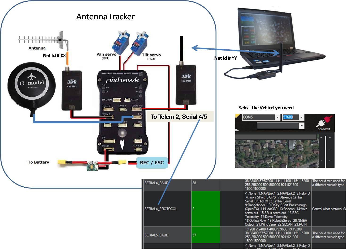
Physical Hardware Setup/Layout
-
Ensure that AHRS orientation is set properly.
-
Make sure all compasses are mounted so that they rotate and tilt with the tracker as it moves.
Calibrating the accelerometer, horizon, or compasses before they are mounted to their final permanent location will make life a nightmare trying to get it to work properly or consistently. ESPECIALLY PID’S! (I learned this the hard way after a full week of fighting to get anything to work) The best option is to have the entire AT rotate around a base. There is a link at the top of this post to the design I created and made with a 3D printer. It works great so far. There is also a file that lists all of the components I used to build it as well as links to the specific ones I bought. A cost breakdown PDF is at the bottom of this post. Depending on what components you may already have, the cost can be less than $100.00 or up to $500.00 if you need to purchase every individual component. -
If external compass is used, make sure its orientation is set properly.
PX4/ArdP automatically makes external compasses priority. For example if your board has two internal compasses, and your GPS module as a compass as well, the board will set the ID’s as follows. Compass 0 = External GPS Compass, Compass 1 = Internal Compass, Compass 2 = Second Internal Compass.
Calibration Procedure for Accelerometer
a. Power up system and allow it to initialize.
b. Arm using safety button on GPS module.
c. Go to flight data screen and put into “STOP” mode using the “Action” menu. You have to click “set mode” after you select whatever option. Go back to Sensor Menu in Initial Setup and select “Calibrate Accel.” If nothing happens after you click “Calibrate Accel,” go back to Action Menu and make sure its in STOP mode, and is armed.
Calibration Procedure for Compass
a. Power up system and allow it to initialize.
b. Arm using safety button on GPS module.
c. Go to “Flight Data” screen and put into STOP mode using the “Action” menu. You have to click “set mode” after you select whatever option.
d. Go back to Initial Setup menu and select compass.
e. Select your board at the top, and make sure your external compass orientation and your board orientation are correct. (look at artificial horizon on flight screen and tilt AT unit to make sure horizon is moving the right direction)
f. Click on calibrate compass….You should see something happen. Green bars or digits appear. Follow standard compass calibration as documented for all other vehicles. If nothing happens after you click “Start Calibration,” go back to Action Menu and make sure its in STOP mode, and is armed.
Simulation Using Live Actual Tracker
-
Open two separate instances of MP. If you have two or more screens, its super helpful. Otherwise you can just do a split screen. Its also ideal to adjust AT settings in real time if you have two separate Sik radio sets. Otherwise, you can connect the AT unit with USB or Bluetooth, just be carful of the rotation limits with the cable. You can always keep the simulated vehicle path limited to whatever your rotation limits with the USB cable are.
-
Power up the AT unit and connect to MP if you wish. Otherwise, just let it do its thing.
-
On the second instance of MP, click the simulation icon.
-
The home location should be the last location MP had when you connected the AT unit. If not, move the map to your actual location, right click the mouse and select “Set Home Here”
-
Select “Plane” For whatever reason, I can never get Multirotor or any of the other Sim vehicle options to work.
-
In the Action Menu, click on “ARM/Disarm” It will probably though a few logging errors, but just ignore them.
-
In the Action Menu, change the mode to “Takeoff” and click “Set Mode”
-
Use your mouse and put it over a location that is directly in front of you, about 200-500 meters out. Right click the mouse and select “Fly to Here”
-
Once the sim vehicle reaches this point, it should start to loiter in a circle.
-
Change the loiter radius in the command box on the left of the screen to 200m.
-
Hold down the Ctrl Key and the F Key to bring up the Temp Menu.
-
Click on “Mavlink” and a serial Output Window will pop up.
-
In the top drop down, Select the Com Port that your Sik Radio is connected to via USB.
-
In the second drop down, select the baud rate for your Sik Radio. It’s most likely 57,600
-
Your Antenna tracker should emit a long tone. This means that it has locked onto the vehicle’s Mavlink signal.
-
Press the “Safety Button” on the AT GPS module. Be carful as it should come to life and start moving.
-
Give the AT unit at least a couple minutes before you start adjusting anything. It will most likely go into scan mode first, then will lock onto the target location.
From this point, you can start adjusting your AT settings for PID, and any other parameters. I highly suggest you unplug the pitch servo at first. Just focus on getting the Pan to function properly first. Once you have that dialed in, move onto the Pitch.
Antenna Tracker Cost Breakdown and Full Parts List Web 1.pdf (47.1 KB)


 . But not how to connect and setup the 3DS Radios together with the MP. Can you help, please?