Z vibes spiking at 60

I’m in the process of testing and perfecting a new quad build.

It’s an 8-10kg quad with 22 inch props running on 6s lipo.

I use the cube orange (non plus).
T-motor MN605-S 320kv with Alpha 60A LV

Log: 2023-06-23 12-19-47.bin - Google Drive

I have an issue where the Z vibrations on the third non isolated IMU spikes very high, around 50-60 but the two isolated IMUs have all vibes around 12.

I’ve recently switched to carbon propps from polymer foldable once. It made the isolated vibes better but the huge Z spike on the isolated IMU wasn’t there before.

I’m kind of lost here and don’t really know what to try next.

Any help is greatly appreciated!

Got a couple of photos of the frame and flight controller?

One of the options is a 3D printed mount like this, usually only required when using a gas powered generator or similar high-vibration environments.

If there’s nothing that can be done for the non-damped IMU you could set this to avoid using it:
EK3_IMU_MASK,3

For your harmonic notch filter you can set these now. The graph below looks like we are missing out one of the harmonics around 220Hz, but you can see from the estimated post-filter graph the attenuation is already good enough to totally filter any of those frequencies and higher.

INS_HNTCH_FREQ,51
INS_HNTCH_BW,15
INS_HNTCH_REF,0.26

I think you’ll recognize this machine since you’ve helped me with it before.

I’ve been tinkering with this one for awhile now trying to perfect it and learn from my mistakes. The cube should ignore the third IMU since the two first has ok values. But I’m a bit afraid that the high mechanical vibration will damage other parts of my frame, such as electronics, wear out mechanical joints and such.

Here’s some pictures of the entire drone and a picture of the internals.

I’m a bit unsure of how small of a thing could cause such a large vibe value. I have mounting rails on the bottom sticking out a little more than 10cm on each side. And my battery cables use an adapter from EC5 to XT90 so there’s some battery cable just hanging around to vibrate. I’m unsure how much those could affect the Z vibrations.

As we have seen on plenty of other craft perhaps the landing gear. That would be difficult to improve w/o a thicker base plate or in some to add rigidity. With that assembly isolation would seem to be problematic. Do those legs have to be that long?

I’m going to perform some tests in a couple of hours.

I could do a flight with the landing gear removed to see if that improves things!

1 Like

That would be very interesting to see.

My landing gears are like a separate assembly. If I remove them they become like a little table the drone sits on top of.

I’ve thaught of adding a dampening system between them like the Alta drones have between their payload and drone. That would eliminate the need for an additional dampening for each payload.

Could that help maybe?

Interesting idea. Might help, might make it worse. Let’s see how it looks w/o the gear.
It might be useful to see the FFT of all the IMU’s before and after you do this. INS_LOG_BAT_MASK,7

The gps masts look pretty tall to me.

They do. Axel-it looks like they are mounted to the bottom plate and bracketed to the top plate. Is that right? That top plate is a huge mass so that would be good.

@jstroup1986 @dkemxr

Yes, my masts are quite tall. I really wanted to get great compass readings. But maybe I over did it. I could cut the down a little bit if needed.

Here’s a picture of the mounting. The two main plates extend to allow for the gps masts and the Herelink antennas to be mounted a bit to the side. There are aluminum standoffs between the two main plates and the Herelink antenna mount and gps mast mount are 3d printed out of PLA.

I could mount a carbon rod between the two masts to change their vibrational properties. Maybe that could make a change.

That looks very rigid to me even if they are waving around. Plus you have the plates boxed out on the sides which would seem to isolate whatever deflection there was to the mounting tabs.
Nice assembly.

The main plate extensions look like a source of Z-axis vibration.

I like those carrier boards, but what I dont like is how they are usually mounted.
I know they are plastic standoffs so not exactly solid, but I would use some antivibrations mounts - not so much for the antivibration properties, but so any flex in the baseplate is not also flexing the circuit board. While the circuit board is relatively hard-mounted to the base plate, it is a structural member (maybe only a tiny bit) and I think this could eventually cause cracks or component problems and unreliability.
And aside from that we’ve seen plenty of cases where the standard Cube Carrier did need to be mounted on antivibration foam - dispelling the myth that they should always be hard-mounted.

Something like these sorts of things - they need not be too soft, firm would be good. It would just be so the carrier board is not a structural part of the copter.
image

I think the bunches of cables across the top of the carrier board would need to be rerouted to the sides, and not touching the carrier board.

@xfacta @dkemxr
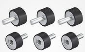
I’ve also thought of using additional dampening. I’ve been avoiding doing so since I don’t know how the cube’s internal dampening would react to it.

I have some more Ideas before I’ll take the copter apart. If possible I would like to avoid that since it’s so much work and I’m afraid to ruin the bolts.

I’ve conducted two more test flights. The first are just in the same configuration as the log I posted at the beginning of this topic. The weather in that log was quite windy and my last flights were dead calm. I wanted to make the results more comparable so I did two flights.

Note: The motor output in the log and the RATE out suggests a slight imbalance. I believe that might be my battery placement since the drone weighs 5kg and 4.5 with no landing gear and batteries weigh around 4.2kg I bet a slight misplacement could result in some noticeable imbalance.

As smart as I am, I also forgot to change the settings you guys suggested… I’ll do those for my next test flights.

This first one is with the landing gear attached and no changes to the drone.

My own analysis: The vibrations here are still below the recommended maximum (30) on both the isolated IMUs but still high as all hell on the non isolated Z axis. I also have a bit increased X vibration in relation to Y. This is with landing gear in their retracted position.

The X and Y are also a bit higher on the non isolated IMU reaching for and a bit abow 30 at one time.

This test-flight is with no landing gear on the drone:

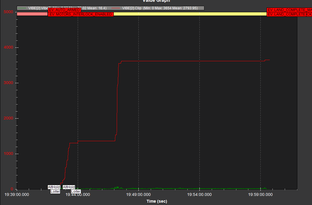
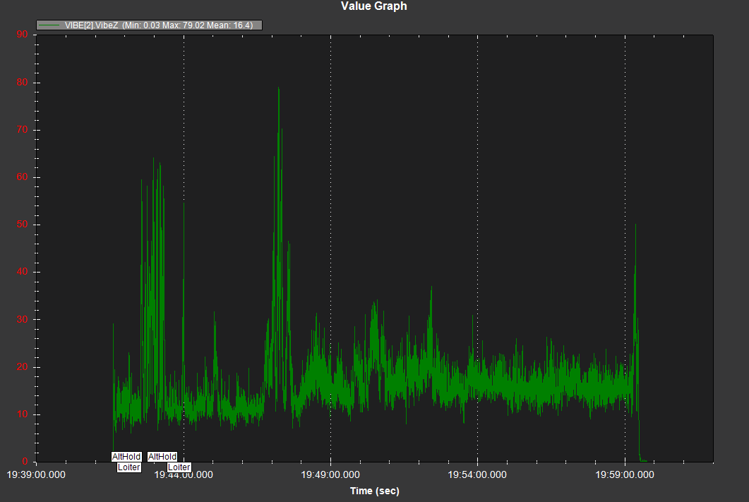
This log is quite long with a long hover at the end. I needed to drain the batteries a bit more down closer to storage level. The isolated vibrations are better here with the Y and Z being really great. The X is much higher in relation but still within a manageable range. There are some vibe spikes that occur with larger pitch and roll input.

The non isolated one is also good on Y and X. The X is lower here than on the isolated one so I might be hitting the cubes internal dampening resonance frequency a bit. The Z is also much better here but I hit spikes that are concerningly high.

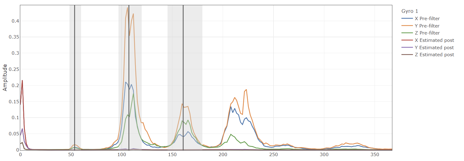
The RATE.out plot also looks less noisy at hover.

So, I have some more tests I could do to gather more test data. I’ve been running the regular T-motor 22inch carbonfiber propps for these tests fitted with the T-motor quick attach adapter.

The adapter came with a wave formed washer I didn’t install, since it got quite hard to push the propp into place with it on. That might have been a mistake and I have installed it on all adapters now. I plan on making a test both with and without landing gear with this washer installed.

I could also make a test with the adapter removed. And attach the propp directly to the motor. This could help since adapters usually are not the best. It would bring the propp very close to the arm which might not be good but still worth a try.

Next I have my old set of foldable polymer propps. I have used those before I got my new carbo propps but maybe I should test them with and without landing gear in the same environment as the other tests just to get the data.

Next step would maybe be to try to fix my gps masts better and see if thty makes ant change at all. just to be sure.

I’m not the best at log analysis so any input is greatly appreciated. I’m sure I’ve missed things!

I think there’s still work to be done on the hardware side. The log show large amounts of clipping on IMU[2] - probably triggered at times when throttling up/down or input - I didn’t look too closely.

Clipping:

Z-Vibration:

I would focus on reducing the Z-vibrations to much lower levels.

I was also experiencing high z vibes played a lot around how the FC is mounted .

Have you used any anti dampers below FC ?

Try to put dead weight on top of cube orange and the FC should be on a double layered anti vibes mount.

It helped in our case