Forgive me if I’m a bit confused by the question. There is one 6-pin GH connector on the SimpleRTK2B board that needs to be connected to a serial port on the cube. You can connect it to one of the 6-pin serial ports labeled GPS2, Telem1, or Telem2. Or, if you’re comfortable repinning a connector, you can use an 8 pin connector on the Cube side and connect it to GPS1 (keep the power, TX, and RX lines on pins 1-3, and use pin 8 for ground).
If you’re looking for a specific connector in the Cube’s wiring kit, it may not exist. They do a good job of packing some frequently used parts, but they don’t include a connector for every possible hardware configuration. You can order more connectors from Amazon, Mouser, DigiKey, etc.
Thanks Yuri, That’s is what I thought but Kenny and I were discussing a cable and I was hoping it was in the Orange Cube set, I ordered a Pre-Crimped Cables and GH1.25 Connectors for Pixhawk2 Pixhack Pixracer PXFmini Silicone 15cm Wire from the AMAZON .and I will make one,Thanks again for all your help on the subject matter You and Kenny are the “MEN”
Thanks for the reply. I just love the way manufacturers change things like the standards for wiring from one model to the next.
“The nice thing about STANDARDS is the are so many to choose from”
Doug
Kenny, do you have a diagram or description of the jumper needed for the co99-f9p boards. I have two of these I plan to use on my 50" cub cadet.
I’ve been using it for 3yrs on 5 acres. with a flysky i6 ,works well but my 67 yr old hands aren’t too steady.
All though I worked on aircraft autopilots. the learning curve for the new acronym’s has been hard! Maybe just old age.
I really appreciate Your and Yuri’s work on these builds. I was wondering if feedback from wheel speed wouldn’t help to eliminate the need for rapid updates to the a/p from gps. because the hyd motors will never run evenly on uneven ground and might help with coordinated turns. No criticism just curious.
Thanks to you both, pls keep up the good work.
I got my GHkit and had to make a all new cable as the contacts on the GH are different from the DF on the old one. Now I am faced with the Telemetry radio I previously used has the same issues. Cables are not compatible with CubeOrange. What telemetry setup are you using with Orange? I cant find the cheap Holybro that was used a couple years ago with GH cables. I can find the RFD900x only
On my mower, I use the Holybro 915MHz radio set that appears to be out of stock everywhere. It has never let me down.
I use this one from Amazon on my Copter, but it appears to have skyrocketed in price, and the build quality is not the same as the Holybro ones.
I recently found this mRo version that I think I’d trust a little more than the one I linked above on Amazon. mRo makes pretty high quality components.
Regardless of source, you may have to do some soldering or terminal crimping to get the connector style you need. While many of these companies endeavor to make things plug and play, there isn’t always a one-size-fits-all solution.
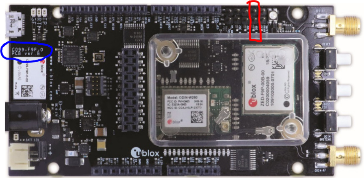
Rustey, I assume you are not planning to use the built-in WiFi communication on the boards. If you are, there are a few more complex changes you have to make. If you are not using that, you only need to install a jumper in the 40E position (circled in red below), assuming you have the same version of the PCB as I do. I think they may have revised it and I am not sure if anything related to jumpers changed. I have had my board since they were first introduced. Putting a jumper on 40E (and NO jumpers on 10E, 20E and 30E) disconnects the F9P UART1 RX line from the ODIN WiFi module and connects it to the Arduino D connector.
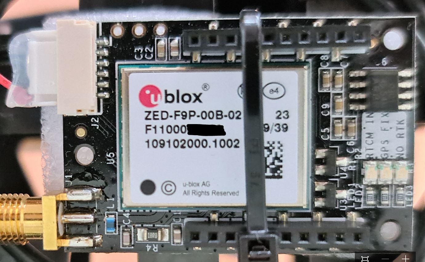
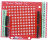
To connect to the a Pixhawk 2.1 (Cube), connect RXD-ZED to GPS1 pin 2 and TXD-ZED to GPS1 pin 3. I’m using an Screw Terminal shield. You can see the white and blue wires from what is labeled as D0 and D1 on the shield to the the GPS1 connector on the Cube. (D0 connects to RXD-ZED and D1 to TXD-ZED no the C099-F9P.)
I’m not sure if you are planning to have both GPSes on the mower so you can have a Moving Base configuration or just what. I’ll be glad to help anyway I can with those connections if you wish. I am running 2 C099-F9P boards on my mower (you can see a bit of the 2nd one at the lower left of the pic above.)
Looking forward to hearing more about your project!
Kenny, Thanks for getting back to me so quick! The pic’s worth a thousand words. I plan to use a moving rover with a fixed base. I do have a later C099-F9P rev. pcb ver E so I’ll have check out the jumpers but I doubt they are different. No I don’t plan to use the on board ODIN module. Plan to use a couple of telemetry radios. tied to my old laptop…base station which I will mount on my wheel chair( a Kubota atv 500) I cannot walk long distances any more. plus I want to be able to chase this thing down In case of catastrophic failure. I’m somewhat out in the country. Not a lot of people around. I learned the hard way that you cannot have enough Fail safes!
I had a typo in my last post age =77 not 67. enjoy your youth!
Best regard’s, Rustey
P.S. want hear more about your sprayer, when you get it started.
I am using GPS yaw on a drone with ArduCopter since several months but until now with relaying the RTCM data between moving base and rover via the Pixhawk Cube Orange. The modules are two ArduSimple SimpleRTK2Blite:
Via Mission Planner I feed RTCMv3 correction data that I get from a fixed base via NTRIP.
During the betas I also went through all these problems with unhealthy GPS etc. and with 4.1.0 beta5 the drone had a crash due to EKF3 position estimation going mad: EKF3 position still going mad in beta5 - drone crashed
Until now it is still not clear what caused this behaviour but one of the countermeasures that I want to take now is to unload the relay traffic through the Pixhawk by directly connecting the two UART2 ports of the ArduSimple modules.
You may instead install a cross-over UART cable between the two UART2 connectors on the two GPS modules. If you do that then you can set GPS_DRV_OPTIONS = 1 which tells the u-blox GPS driver to configure the two GPS modules to send RTCMv2 data over UART2.
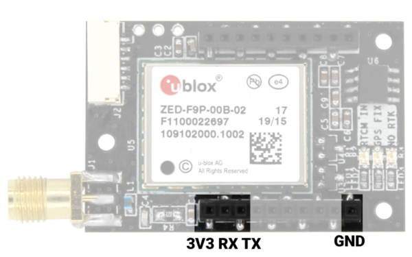
Do I understand it right, that only one wire is required? Going from the TX2 port of the moving base to the RX2 port of the rover?
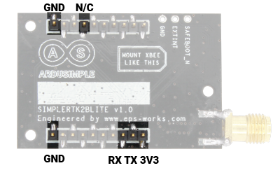
On the modules, I see no marking. As it was mentioned here that RX and TX are mislabeled on the SimpleRTK modules, is this the correct mapping?
UART1:
UART2:
The pictures were taken from the ArduSimple documentation at simpleRTK2Blite hookup guide - ArduSimple
In my opinion this must be wrong - both pictures seem to show the same UART (but one is from the bottom and one is from the top side, connectors going through).
Would it work to piggyback these modules?
Will the moving base still consider the RTK correction data coming from the ground via Mission Planner MAVLink messages?
First, I’m inclined to trust the ArduSimple documentation regarding the pinout. Those look like surface mount headers and sockets (note the solder left or right of each pin), so they probably do not connect through the board. Thus UART1 is exposed on the pin side and UART2 is exposed on the socket side if we are to believe the documentation.
However, the documentation still has the TX/RX labeled in a counterintuitive way. If you look at the XBee pinout, XBee TX (data out) is adjacent to 3v3. As such, the ArduSimple board actually receives data on the socket labeled TX and transmits on the socket labeled RX.
So, connect a wire from the RX-labeled socket of GPS1 to the TX-labeled socket on GPS2 and set GPS_DRV_OPTIONS=1. There will be no effect on UART1/MAVLink RTCM3 injection, and you should get more reliable RTCM3 from the moving base to rover.
You might get away with piggybacking the boards if the rover is the one on top. You’d still set GPS_DRV_OPTIONS=1 to do so.
@Hacky, I think @Yuri_Rage has answered perfectly. It is interesting that you have two SimpleRTK2Blite modules rather than two SimpleRTK2Bs or one of each. As long as both UARTS are exposed somehow on the Lite modules, you certainly should be able to connect them just like the full modules. You just don’t have the slight benefit of using Arduino screw terminal shields or similar, which I really love for external wiring.
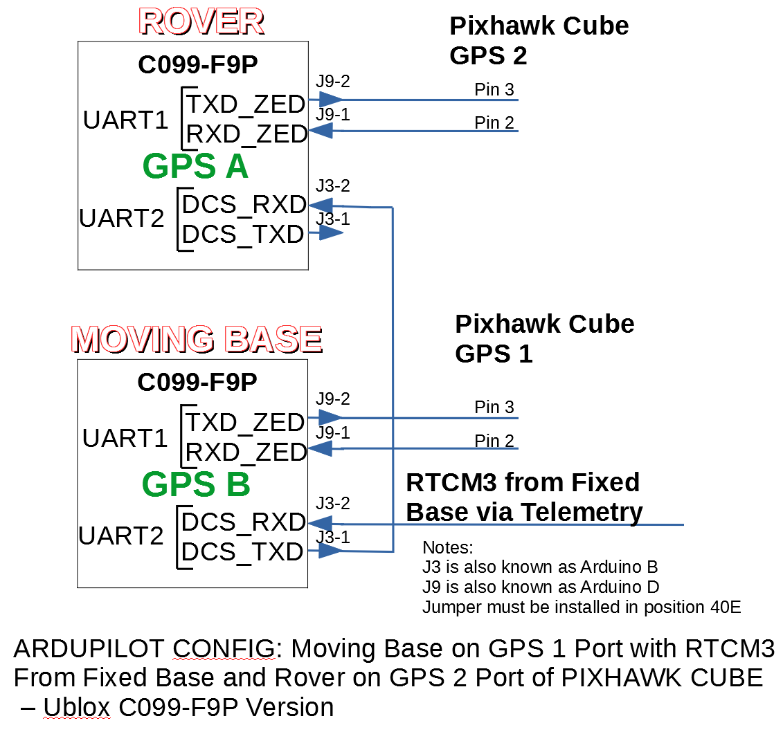
Hey Rustey, that Cub Cadet looks ready for action. I have attached my current parameters. If you connect both the Moving Base and Rover GPSes via their UART1 ports to the Cube, you do not have to configure the GPSes. Ardurover will do that for you.
How are you planning to get the RTCM3 corrections from NTRIP into your moving base? Are you going to use Mission Planner with MAVLink Injection? Here are my parameters currently in use: 2021-08-29 4-1-0rc1.param (15.3 KB)
You should only use them for reference, of course, since your servos will not behave just like mine and your GPS antennas and flight controller locations will be different, etc.
If you are using C099-F9Ps, this will help you with which pins to connect to the Cube:
Note that if you are using MAVLink injection, you will not have the connection to J3-2 on the Moving Base. Also, note that you need to put a jumper on position 4OE, and no other positions.

 or similar, which I really love for external wiring.