X11 max Motors beeping

Hello guys, I hope you all have great time. I just bought x11 max motors, did wiring and etc. with guy who knows, what need to be where. I installed the firmware, but I face a problem. It’s my first time making big drone to launch, soo it’s hexa with orange cube, I plug in motors 1-1 2-2 and etc. and i have been left with rcin and another one, when I was building quad one wire was goin in 8 and I was putting on servo outputs RCIN9. Now i have 8 and RCIN, motors beeping, I know, that problem is because of one setting. so maybe, someone could tell me more information about RCIN outputs, what they doing, why is that. I surf basiclly all internet but my didn’t found much information. Thank you

Tautvydas.

RCIN is not an output. Like the name says it’s “remote control input” . You need to connect the output of your remote controller receiver to it. It is not a motor output and it is not a servo output.

Okay, so motors could beep because of ESC values? cause I didn’t touch ESC calibration section yet.

Have you gone through the complete setup as outlined in the documentation?

Could you send a picture of all your inputs on the cube?

The RC in port is for your receiver. No ESC should be plugged in there. If you have a normal receiver like an FRsky or Futaba the S.bus signal goes into the RC in port. For all the ESCs, you should be using the main outputs 1-8. If you d-shot you should be using the AUX, but I think the hobbywing uses normal PWM so MAIN 1-8 should be used.

The reason they beep could be that you haven’t set the PWM range correctly. I think the hobbywing X11 has a fixed pwn range so no ESC calibration is needed. I found one page that said 1050-1950. This could be correct but check with your supplier as I’m not totally sure. The settings for this is the MOT_PWM_MIN for the lower value and MOT_PWM_MAX for the higher value. After that you will need to use the motor test feature to determine the MOT_SPIN_ARM and MOT_SPIN_MIN parameters. There’s instructions on the wiki on how to do this.

Hope it helps

The ESC beeping will only stop when they receive a valid PWM signal, such as when the flight controller is armed.
Beeping alone is not an issue yet.
Motor Test is your friend - and when you think you’ve got everything right, check again, and again…

Set MOT_PWM_MIN = 1050/1100
Set MOT_PWM_MAX = 1950/1940

I put those, beeping didn’t gone, i can’t arm can’t even check motors in motor test. Sooo yeah, issue still here, i will give you some beeping video, photo of my cube, and servo output settings and esc calibration section.

Tautvydas

I feel like this was ignored…

Ohhh sorry, yup i did everything what said in ardupilot

What are the error messages when you try to arm?

Damn… I forgot, I was looking at it but I forgot, the thing is, one guy who build up quad to me, put rcin9 at section 8 in servo output, when i put that on disable in my small drone, almost the same beeping, so I wondering, there is 8 and RCIN plugs, the guy who build it said it needs to be like this but he didn’t told me why. so I don’t know what to put there, I’m pretty sure there is the problem

Hey guys, drone standing still and I dont know what to do, waiting for you guys to answer if someone know haha…

You just need to follow the documentation and read through the sections on wiring it up and first flights.

I cant tell much from those screenshots and a video of motors beeping.

The motors will not stop beeping until the copter is armed for flight, without changing more settings.

Set this in the Full Parameter List:

LOG_DISARMED,1
BRD_SAFETYENABLE,0
MOT_SAFE_DISARM,0

This will disable the safety switch operation and stop the ESCs and motors from beeping, and more importantly it will generate a .bin log file. Let the copter sit for a few minutes to get a good log.
You can download the .bin log file from the copter, then upload to your filesharing service and send a link.
Then set: LOG_DISARMED,0

Did RC Calibration work OK?

Hello @xfacta i did some idle standing, tested motors, it started to spin, everything looks fine, I didn’t do much today, because i was busy, so I did what you said, and now sending link for you to check. By the way, RC calibrated, I tried to arm, and now compass not calibrated so yeah, I understand that problem for sure! :laughing: soooo, next step from first flights page yup ? Motor deadzone and etc. ? Link here >

Tautvydas

Hello ? I still waiting, I can bet you have more experience than me, so I still waiting haha

Tautvydas

You have: “PreArm: Compass not calibrated”
So take the whole rig, copter and ground station, outside and wait for a good GPS 3D Fix, then do the compass calibration.

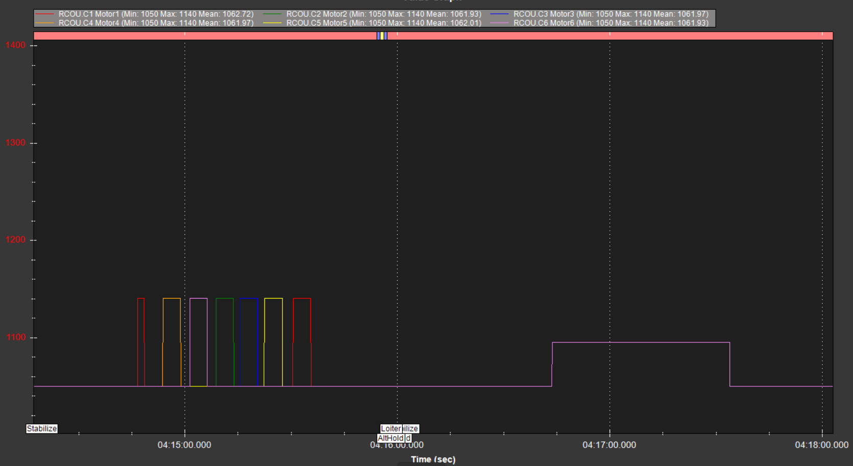
In that latest log we can see the motor tests so that is something.
If that didnt produce any spinning motors then the ESCs are not connected properly.

The frame type is set to a Hexa+ so make sure this is how the frame really is compared with Flight Controller orientation

image

the more typical configuration is HexaX

image

So be sure about that physical configuration before going further - the motor order and numbering is quite different.

See those motor numbers in the diagrams - they (or their ESCs) need to be connected to the Flight Controllers Main Out servo connectors with the same numbers - dont be confused by the Aux Out pins, ignore those for now. So Motor1 connects to MainOut 1 servo connector on the flight controller, and so on.

image

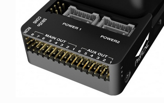
On the side of the carrier board with be " - + S "
The ground wire from each ESC, usually black, connects to it’s main out TOP ROW pin indicated by the minus sign.
The signal wire, usually white, connects to it’s main out BOTTOM ROW pin indicated by the S.
There should be nothing connected to the centre row of + pins.

For SAFETY take the props off, put some tape on the motor shafts or some indicator so you can easily tell which way they spin.

Now go back to MissionPlanner motor test and check all the motors work in the correct order. In motor test they have letters A, B, C … starting at front/right and going around clockwise.

image

Once the motor order is correct, then change the spin of any motors if required, to match the clockwise or counter clockwise arrows in the diagram.

DO NOT go out trying to fly this copter yet
Next step is to get the battery voltage and current monitor working. This is quite important for safety and also helps tuning and stability.
You probably just have to go to the Full Parameter List and set
BATT_MONITOR 4
for voltage and current. Reboot the flight controller.
If you have the voltage sensor and regulator that came with the Cube then it should probably just work. In the MissionPlanner HUD you should now have a realistic, almost exact, battery voltage displayed when the battery is connected.

Let us know when you’ve done all that and we’ll move on to more steps before flight.