Write multiple bytes on I2C

How can I write multiple bytes to an I2C device? The only thing I found is to write exactly two with “write_register” (where I find the distinction between register address and value a bit arbitrary, it’s all just bytes and if the first is logically even a register address depends on the sensor).

My usecase: I want to use a Bitcraze Multi-ranger deck. It has 5 VL53L1x ToF sensors and a PCA9534 I2C IO expander connected to their resets. After powerup all the sensors have the same I2C address, but it can be changed via an I2C command. For that you use the PCA9534 to bring them out of reset one after another and change their address. Controlling the PCA9534 is fine with LUA and I can toggle the reset lines one after another. But for setting a VL53L1’s address I need to send three bytes in one go (“0x00”, “0x01”, “”). How do I do that?

At the moment, I don’t think you can send three consecutive bytes like that (though maybe two consecutive writeregister calls may be interpreted by the device that way - I kind of doubt it).

If the address is stored in non-volatile memory, you might try connecting it to another device like an Arduino or ESP board, writing the address, and then using it with your script.

Otherwise you may be stuck using an intermediate microcontroller to interpret scripted messages and send sensor values back. See here for an example:

Rationale provided by @iampete in this topic:

If you’re willing to build your own firmware, you could write a custom binding to transfer 3 bytes. Unfortunately, I don’t think that’s practical for inclusion as a PR at the moment for the reasons provided in the linked topic.

I tried that already, but as expected it does not work.

Unfortunately it is stored in volatile memory only.

That’s what I wanted to avoid since I’m literally one byte away from a solution. Though even an attiny10 (6 pin SOT23-6 package) should be able to do it, I’d still have to “split” the I2C bus with all the support circuitry, while I’d rather have the flight controller do the work.

There are write_register16 functions in AP_RangeFinder_VL53L0X and AP_RangeFinder_VL53L1X (confusingly with different signature - (uint8_t reg, uint16_t value) for the L0X, (uint16_t reg, uint16_t value) for the L1X), that would send 3 or 4 bytes respectively. How can those be (ab)used in LUA?

Check out the documentation on adding bindings. It’s reasonably straightforward once you get a handle on the binding generator syntax. You’ll have to have a build environment set up.

we can now mix manual and auto generated bindings, so it is possible to add a manual binding for a variable number of bytes.

1 Like

Then I retract my statement about not making a PR. We should probably add some functionality here.

Would benefit very much from this functionality as well. A read function as well would be useful for sensors that have multiple byte registers.

My workaround with an attiny10 and a few MOSFETs for my specific case. Just because of one byte I couldn’t write :laughing:

//                         +-\/-+
// LINK I2C --- (A0) PB0  1|°   |6  PB3 (A3) --- Reset
//                   GND  2|    |5  Vcc
//      SCL --- (A1) PB1  3|    |4  PB2 (A2) --- SDA
//                         +----+  
//
// Controller:  ATtiny10
// Clockspeed:  8 MHz internal, clockdiv 8


#include <avr/io.h>
#include <avr/power.h>
#include <avr/sleep.h>
#include <util/delay.h>

#define I2C_SDA         PB2                   // SDA pin
#define I2C_SCL         PB1                   // SCL pin
#define I2C_LINK        PB0                   // controls the MOSFETs that link the I2C busses
#define I2C_SDA_HIGH()  DDRB &= ~(1<<I2C_SDA) // release SDA   -> pulled HIGH by resistor
#define I2C_SDA_LOW()   DDRB |=  (1<<I2C_SDA) // SDA as output -> pulled LOW  by MCU
#define I2C_SCL_HIGH()  DDRB &= ~(1<<I2C_SCL) // release SCL   -> pulled HIGH by resistor
#define I2C_SCL_LOW()   DDRB |=  (1<<I2C_SCL) // SCL as output -> pulled LOW  by MCU

#define SENSORS 5

#define ADDR_PCA9534 (0x20<<1)
#define ADDR_VL53L1X (0x29<<1)

uint8_t xshut_pins[SENSORS] = {0,1,2,4,6}; // order: up, back, right, front, left
uint8_t xshut_pins_mask = 0b10000000; // alternative: output 7 will be used to link the I2C busses via MOSFETs
uint8_t xshut_pins_set  = 0b00000000;

// I2C transmit one data byte to the slave, ignore ACK bit, no clock stretching allowed
void I2C_write(uint8_t data) {
	for(uint8_t i = 8; i; i--) {            // transmit 8 bits, MSB first
		I2C_SDA_LOW();                      // SDA LOW for now (saves some flash this way)
		if (data & 0x80) I2C_SDA_HIGH();    // SDA HIGH if bit is 1
		I2C_SCL_HIGH();                     // clock HIGH -> slave reads the bit
		data <<= 1;                           // shift left data byte, acts also as a delay
		I2C_SCL_LOW();                      // clock LOW again
	}
	I2C_SDA_HIGH();                         // release SDA for ACK bit of slave
	I2C_SCL_HIGH();                         // 9th clock pulse is for the ACK bit
	asm("nop");                             // ACK bit is ignored, just a delay
	I2C_SCL_LOW();                          // clock LOW again
}

// I2C start transmission
void I2C_start(uint8_t addr) {
	I2C_SDA_LOW();                          // start condition: SDA goes LOW first
	I2C_SCL_LOW();                          // start condition: SCL goes LOW second
	I2C_write(addr);                        // send slave address
}

// I2C stop transmission
void I2C_stop(void) {
	I2C_SDA_LOW();                          // prepare SDA for LOW to HIGH transition
	I2C_SCL_HIGH();                         // stop condition: SCL goes HIGH first
	I2C_SDA_HIGH();                         // stop condition: SDA goes HIGH second
}


int main(void) {
	//clock_prescale_set(clock_div_1);

	DDRB  |=  (1<<I2C_LINK); // set I2C link pin as output
	PORTB &= ~(1<<I2C_LINK); // I2C link low disconnects I2C busses

	DDRB  &= ~((1<<I2C_SDA)|(1<<I2C_SCL));  // pins as input (HIGH-Z) -> lines released
	PORTB &= ~((1<<I2C_SDA)|(1<<I2C_SCL));  // should be LOW when as ouput

	for (uint8_t i = 0; i < SENSORS; i++) {
		xshut_pins_mask |= 1 << xshut_pins[i];
	}

	I2C_start(ADDR_PCA9534);
	I2C_write(0x01); // prepare low outputs
	I2C_write(0x00); // prepare low outputs
	I2C_stop();

	I2C_start(ADDR_PCA9534);
	I2C_write(0x03);             // enable outputs on P6,4,2,1,0 (active low)
	I2C_write(~xshut_pins_mask); // enable outputs on P6,4,2,1,0 (active low)
	I2C_stop();

	for (uint8_t i = 0; i < SENSORS; i++) {
		xshut_pins_set |= 1 << xshut_pins[i];

		I2C_start(ADDR_PCA9534);
		I2C_write(0x01);           // enable next sensor
		I2C_write(xshut_pins_set); // enable next sensor
		I2C_stop();

		_delay_ms(10);     // wait for sensor to get ready

		I2C_start(ADDR_VL53L1X);
		I2C_write(0x00);   // change address
		I2C_write(0x01);   // change address
		I2C_write(0x30+i); // change address
		I2C_stop();
	}

	for (uint8_t i = 0; i < SENSORS; i++) {
		I2C_start((0x30+i)<<1);
		I2C_write(0x00); // DEBUG: to check for ACK on logic analyzer trace (successful address change)
		I2C_stop();
	}

	I2C_start(ADDR_PCA9534);
	I2C_write(0x01);                        // link I2C busses with PCA9534 pin 7 (unused alternative)
	I2C_write(xshut_pins_set | 0b10000000); // link I2C busses with PCA9534 pin 7 (unused alternative)
	I2C_stop();

	PORTB |= (1<<I2C_LINK); // I2C link high connects I2C busses

	power_timer0_disable();
	power_adc_disable();
	set_sleep_mode(SLEEP_MODE_PWR_DOWN);
	sleep_enable();
	sleep_cpu();

	while (1) {
		asm("nop");
	}
}

2 Likes

I have done a PR for multi byte read, multi byte write would be done in much the same way.

2 Likes

Awesome, very much appreciate it @iampete. Is there a firmware build with these updates?

Its merged into master so can be found on the firmware server under latest. EG for copter:

https://firmware.ardupilot.org/Copter/latest/

It is a dev build so there are other changes compared to a stable release.

1 Like

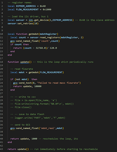
Hey @iampete I upgraded the firmware and loaded my script but got the error: bad argument to "read_registers ('argument out of range). I’m specifying 2 as the read_length input to indicate 2 bytes to be read. Here is my function:

image

That should work, what board are you on? Maybe you could post the full script?

@iampete I’m using CUAV v5+. Here is the full script: sfm3300-flow-meter.lua (1.0 KB)

The out of range is on the register number. The problem is that you don’t actually want to read registers. Your reading, but not from a register. You also need to setup the sensor to begin streaming data.

With some poking about you may be able to get it to work with the existing bindings, or we may have to add some more.

I see, this would probably be nontrivial for me to figure out. Is this something you would be able to look into? Happy to pay for it if the functionality is unique to my application and less useful to others. Thanks

Hi @iampete. I’m having a little trouble with i2c multi byte read.
I’m trying to write a lua driver for an MCP9808 temperature sensor. It’s very similar to the MCP9600 wich you already support.

The device is definitely streaming, the readings stay stable and when I blast it with a heat-gun they do go up, but the reading does not change as much as it should and I’m getting very unlikely values.

Page 33 of the data sheet specifies some other registers with expected values, the expected values are as follows:

address ->> expected value
0x05 ->> variable (this is where we expect to find the 16 bit temperature)
0x06 ->> 0x0054 (hex)
0x07 ->> 0x0400 (hex)
0x08 ->> 0x03 (hex)

my minimal script is as follows:

local MCP9808_ADDR_0 = 0x18

-- bus, and device address
local i2c_bus = i2c:get_device(0,MCP9808_ADDR_0)
i2c_bus:set_retries(10)

function update() -- this is the loop which periodically runs

    i2c_bus:set_address(MCP9808_ADDR_0)

    bytes = i2c_bus:read_registers(0x05,1)
    gcs:send_text(0,"0x05:  " .. tostring(bytes))

    bytes = i2c_bus:read_registers(0x06,1)
    gcs:send_text(0,"0x06:  " .. tostring(bytes))

    bytes = i2c_bus:read_registers(0x07,1)
    gcs:send_text(0,"0x07:  " .. tostring(bytes))

    bytes = i2c_bus:read_registers(0x08,1)
    gcs:send_text(0,"0x08:  " .. tostring(bytes))

    gcs:send_text(0,"----")


    return update, 1000 -- reschedules the loop
end

return update() -- run immediately before starting to reschedule

With no read length specified I seem to reliably get the msb of the regisers and my print outs are as follows:

0x05:  193 (up to 200 if I cook the sensor)
0x06:  0 # expected 0x0054
0x07:  4 # expected 0x0400
0x08:  3 # expected 0x03

With a read lenght of 1, my results are as follows:

0x08:  table: 0x2000BE18 (value alternates, which is not expected)
0x07:  table: 0x2000B850 
0x06:  table: 0x2000B658 
0x05:  table: 0x20007998 
----
0x08:  table: 0x2000BF88
0x07:  table: 0x2000B850
0x06:  table: 0x2000B658
0x05:  table: 0x20007998

With a read lenght of 2, my results are as follows:

0x08:  table: 0x2000ADD0 (again the value alternates)
0x07:  table: 0x2000A758
0x06:  table: 0x2000A4D0
0x05:  table: 0x200067E0
----
0x08:  table: 0x2000ADF8
0x07:  table: 0x2000A758
0x06:  table: 0x2000A4D0
0x05:  table: 0x200067E0

Since the values in 0x08 arn’t supposed to change and do when we add the second argument to i2c_bus:read_registers, i’m assuming that something is going wrong.

Any ideas?

log_2_UnknownDate.zip (460.3 KB)

Try this:

    local ret = device:read_registers(0x05,2)
    if ret then
      local t = ret[1] << 8 | ret[2]
      temp = t & 0x0FFF;
      temp = temp / 16.0;
      if (t & 0x1000) ~= 0 then
        temp = temp - 256;
      end
      gcs:send_named_float(name, temp)
    end

@iampete you’re the man! thanks.