We flew our first mission today using QGroundcontrol as the mission planner. Flight was about 800m around a headland with a bit of a breeze. We used spline waypoints. Flight was fine until the end when the quad decided to yaw wildly and did a few 360’s before heading home to land OK . I have attached the log.
I suspect that the wind made the motor output high in the final part of the mission and this created magnetic interference with the compass and hence the wild spinning.
I’m far from being an expert, but happy to take a look because it helps me too, and it’ll be a nice bonus if I can help you too.
I’m not experienced with Oneshot125, but it’s looking like RCOUT.C4 (motor 4) is going to its minimum for large stretches of time as if there’s a major weight imbalance or something moved in flight. The craft may be overpowered and losing some authority?? Maybe post some specs.
There’s no large RC inputs to change Yaw, but there’s plenty of RC noise on channel4 around the time of the yaw issues, so it might be someone trying to correct, unsure… Without a log of an ordinary flight I cant tell what your RC channel 4 should normally be doing - there’s that inexperience again.
Yaw is closely tracking Desired yaw, so it’s commanded like the flight controller is compensating for something, unless point 2 above means the transmitter was commanding the yaw and you didn’t know.
Vcc looks low to me, and a bit too noisy. 4.8 volts is too close to brownout, you’re only averaging about 4.9 volts with spikes to 5 volts. It really should be around 5.2 volts constant to be safe.
Compasses look consistent, except where the was compass switching between waypoints 6 and 7 - wouldn’t surprise me if it was related to point 4.
Probably best to run the compass motor calibration. Also current draw looks very low to me, are you sure the current sensor calibration is correct? It could just be me though, I’m used to a quad that draws around 18amps to hover. Specs would help to understand that better.
I’d probably start with sorting out the Vcc (5 volt supply), checking the current sensor calibration and run the compass motor calibration - although none of those may be the cause or the fix they will be good insurance.
I’d redo the RC calibration too, it seems like channel 4 (yaw) is very touchy. Maybe increase the deadzone, RC4_DZ, or add a bit of yaw expo in the transmitter so small yaw stick movements don’t have much effect.
Edit: I’m happy for experienced people to point out my rookie errors to, and ultimately help rustymarmot
Wow that great feedback. Thanks
1/ I think you are correct on the weight imbalance. It was forward heavy. I forgot to adjust for the weight of the camera. It was probably not an issue for the first part of the flight but became an issue in the later stages as a stiff breeze picked up.
I will rebalance and recal the RC and ESC’s.
2/ I have noted the very noisy VCC and just thought is was normal. I will run a few checks but I am using the standard power unit from MRO.
3/ I have been holding off on compass motor cal until the form of the quad is finalised. I may move things around a bit.
My Vcc is averaging at 5.299 with a lower end of 5.28 , and the occasional spike downwards to 5.24 at worst. That was after some “work” on the power distribution board and connectors to the flight controller.
If there doesn’t appear to be anything wrong with the voltage regulator or connectors and wiring, try temporarily unplugging external devices from the pixracer, like GPS, and see what that does to the voltage. If something is pulling the voltage down then run it from a separate BEC.
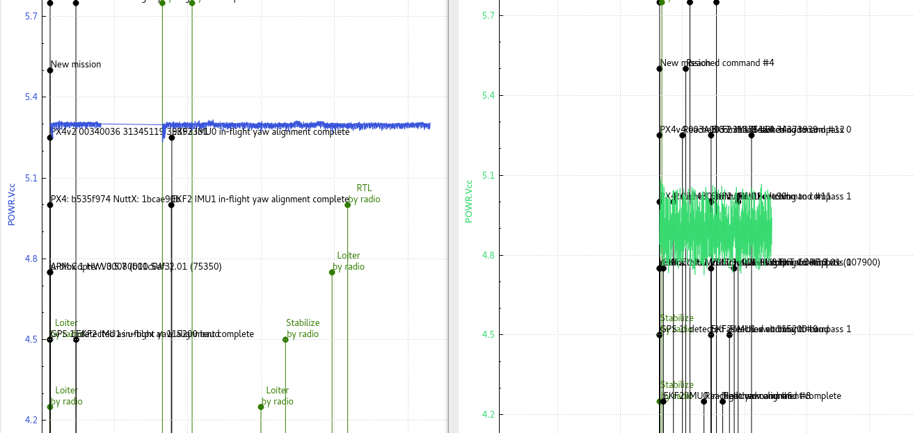
Here’s a pic of my (blue) and your (green) Vcc side-by-side with the same vertical scale
I have started tp try and work through the issues startung with the VCC voltage.
Unplugged GPS. VCC voltage still about 4.9
Unplugged Telemetry. VCC voltage still about 4.9
Checked voltage coming directly off the AUAV ACSP5. The voltage from each of the 5 wires ground wires starting from the wire close to the positive wire is as follows.
Wire 1: Positive wire.
Wire 2: 0.00v
Wire 3: 4.92v
Wire 4: 4.12v
Wire 5: 5.28v
Wire 6: 5.28v
Check your wiring diagrams, the middle two are Current sense and Voltage sense.
I had to add an electrolytic capacitor to my power distribution board 5V output, and directly solder wires to the board and the pixfalcon - bypassing the original JST-SH connectors altogether. That’s a bit extreme though and not for everybody. Maybe just a new cable??
I think the pixracer has slightly bigger/better connectors than the pixfalcon.