My main question relates to driving an autonomous differential drive rover between 2 waypoints and staying on the track between the two waypoints
I have built an autonomous grass mowing machine for my garden. We wrote the code from the ground up. I have used pixhawk in the past but could not get it to work for our needs. Its written in C++ Arduino code. Coding is not my speciality.
It is set up to mow lanes that are 17 inches apart due to the blade size. All the software does is drives our chassis up a lane to a waypoint and then makes a 180 degree turn and drives down the next lane to the next waypoint which is located 17 inches over to one side of the first waypoint.
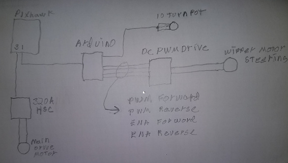
It uses a pair Ublox C94 M8P RTK gps with a reliable AHRS compass (with very little distortion due to magnetic or ferrous material). The vehicle follows waypoints by calculating the difference between the target heading (maths and the gps) and the actual heading (compass) and it uses the difference to send a value in a drive command to the motor controller that alters the speeds to the 2 driving wheels. this variable is called turnSpeed. the chassis is differentially driven.
After many months of work the mower drives well. The heading errors are generally below 5 degrees. However if the mower for some reasons gets off the straight line track between the 2 waypoints the code does not do a good job of getting the mower back on the straight line track quickly as it is aiming at a distant waypoint. In short, it is good at heading to a distant point but not good at getting on the straight line track between the 2 way points and then heading to the point
In order to solve this we started calculating a cross track distance error. And we use a set point of 0 cross track error and a PID to try to get the vehicle back on the straight tract between the two waypoints.
The problem now is that we have 2 inputs to the motor command variable turnSpeed. One from the heading error and the other from the PID. So this is getting real confusing.
Normally I would use the heading error variable if the heading error is greater than 2 degrees. To get the PID tuned I eased off the heading error so that the heading error only works if the heading error is more than ±20 degrees. I set Ki and Kd to zero and increased Kp until the mower went in to a stable oscillation.
I then timed the period of the oscillation for 1 complete wavelength it was 6 seconds.
I then used the following
New Kp= Kp*0.60
New Ki = Period/2
New Kd = Period/8
this gave Kp=5
ki= 3
Kd= 0.7
before this I did many other runs and got poor control response. After running this the mower is still in an oscilation.
I would really appreciate some help here.
1 what are the general mathematical concepts that need to be employed to drive a differential drive robot along a straight path between 2 waypointsand minimize the cross track error.
2 Can we expect our method to work when with have 2 inputs to the same variable, heading error and the PID
3 Do you have a rule of thumb method to tune the PID
Any help on this will be appreciated
regards
Max
PS Max, you don;t have to be sorry to be new on the site. Welcome welcome, thirst for knowledge and understanding is what we do here!
I have built an autonomous grass mowing machine for my garden. We write the code from the ground up. Its basically C++ Arduino code. Coding is not my speciality.
It is set up to mow lanes that are 17 inches apart due to the blade size. All the software does is drives our chassis up a lane to a waypoint and then makes a 180 degree turn and drives down the next lane to the next waypoint which is located 17 inches over to one side of the first waypoint.
It uses a pair Ublox C94 M8P RTK gps with a reliable AHRS compass (with very little distortion due to magnetic or ferrous material). The vehicle follows waypoints by calculating the difference between the target heading (maths and the gps) and the actual heading (compass) and it uses the difference to send a value in a drive command to the motor controller that alters the speeds to the 2 driving wheels. this variable is called turnSpeed. the chassis is differentially driven.
After many months of work the mower drives well. The heading errors are generally below 5 degrees. However if the mower for some reason gets off the straight line track between the 2 waypoints the code does not do a good job of getting the mower back on the straight line track quickly as it is aiming at a distant waypoint. In short, it is good at heading to a distant point but not good at getting on the straight line track between the 2 way points and then heading to the point
In order to solve this we started calculating a cross track distance error. And we use a set point of 0 cross track error and use a PID to try to get the vehicle back on the straight tract between the two waypoints.
The problem now is that we have 2 inputs to the motor command variable turnSpeed. One from the heading error and the other from the PID. So this is getting real confusing.
Normally I would use the heading error variable if the heading error is greater than 2 degrees. To get the PID tuned I eased off the heading error so that the heading error only works if the heading error is more than ±20 degrees. I set Ki and Kd to zero and increased Kp until the mower went in to a stable oscillation.
I then timed the period of the oscillation for 1 complete wavelength it was 6 seconds.
I then used the following
New Kp= Kp*0.60
New Ki = Period/2
New Kd = Period/8
this gave Kp=5
ki= 3
Kd= 0.7
before this I did many other runs and got poor control response. After running this the mower is still in an oscilation.
I would really appreciate some help here.
1 what are the general concepts that need to be employed to drive a robot along a straight path between 2 waypoints. Especially to get back on. This is my main question. You seems to have cracked this very well
track if it gets off track
2 Can we expect our method to work when with have 2 inputs to the same variable, heading error and the PID
3 Do you have a rule of thumb method to tune the PID
Any help on this will be appreciated
regards
Max
PS Max, you don;t have to be sorry to be new on the site. Welcome welcome, thirst for knowledge and understanding is what we do here!