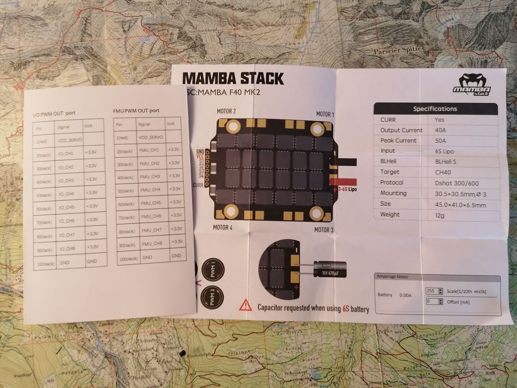
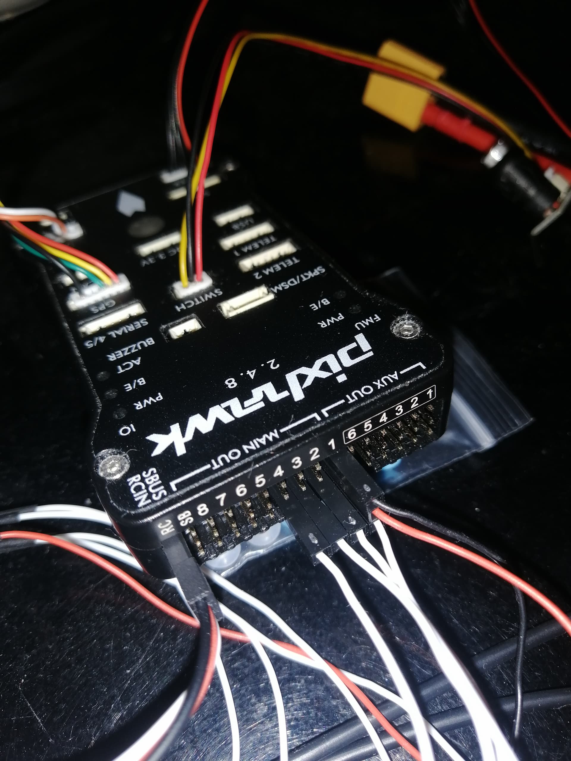
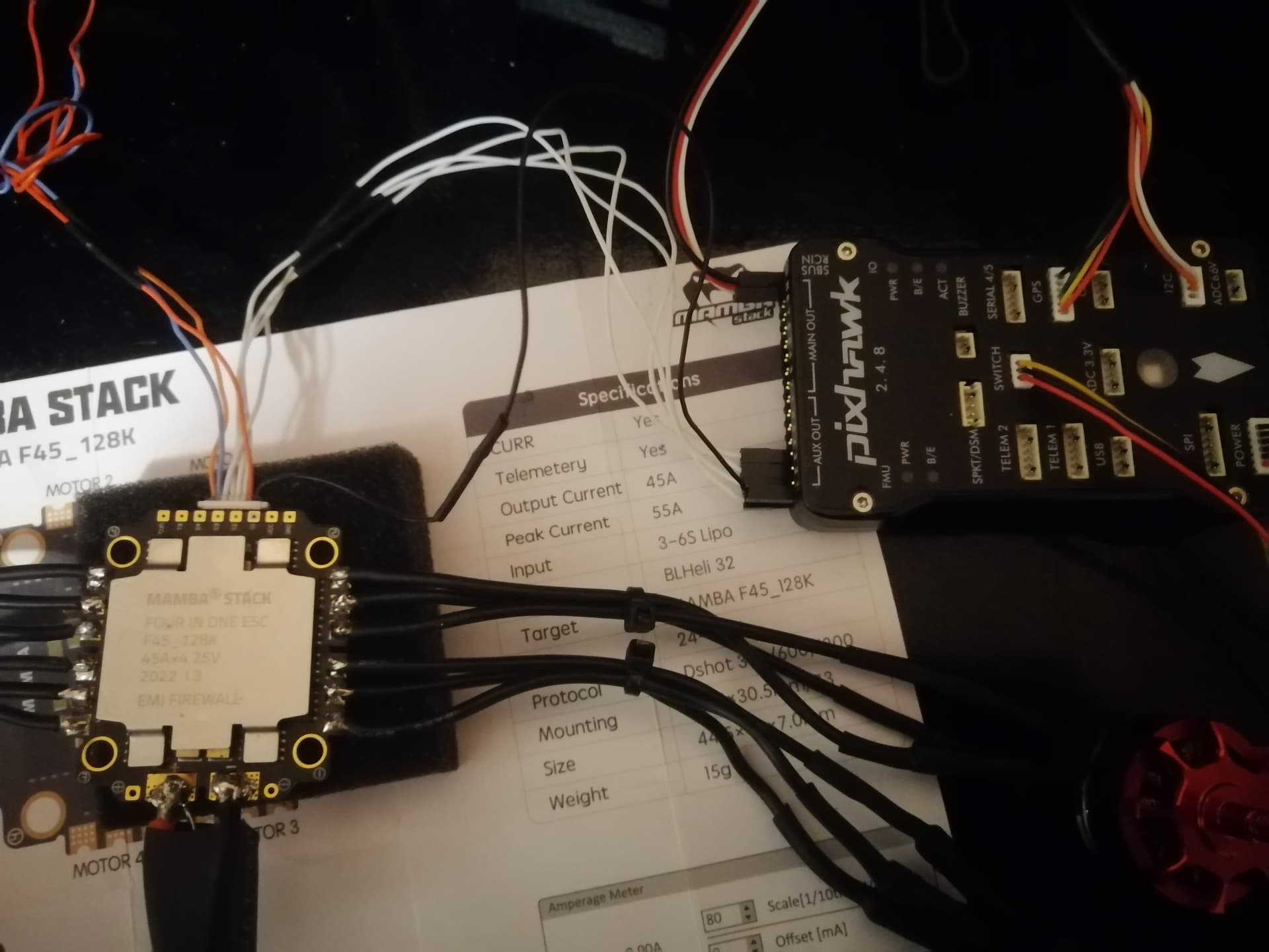
I´m trying to connect my Pixhawk 4 to a Mamba F40 MK2 ESC. The wiring and configuration should be no Problem.
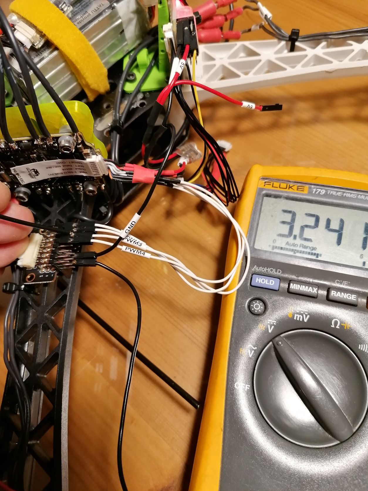
Before I connect or power anything, I first measure the voltage and so I came across something: when I connect a lipo to the ESC, I can measure a voltage between GND and the signal inputs S1-S4 of the ESC. The voltage is 3.2V. Is that normal? I mean, these are inputs for the motor signals and no outputs. I didn’t really expect any voltage there.
Of course I’m a bit confused now and afraid to connect the signal inputs to the Pixhawk’s FMU outputs. Maybe I’m paranoid, or nobody before me has ever measured these points Of course I don’t want to destroy my hardware.
To be on the safe side, I also measured a second ESC, and here, too, 3.2V can be measured at the inputs with the LIPo connected.
Does anyone know this phenomenon? Do I need to worry or can I connect everything?
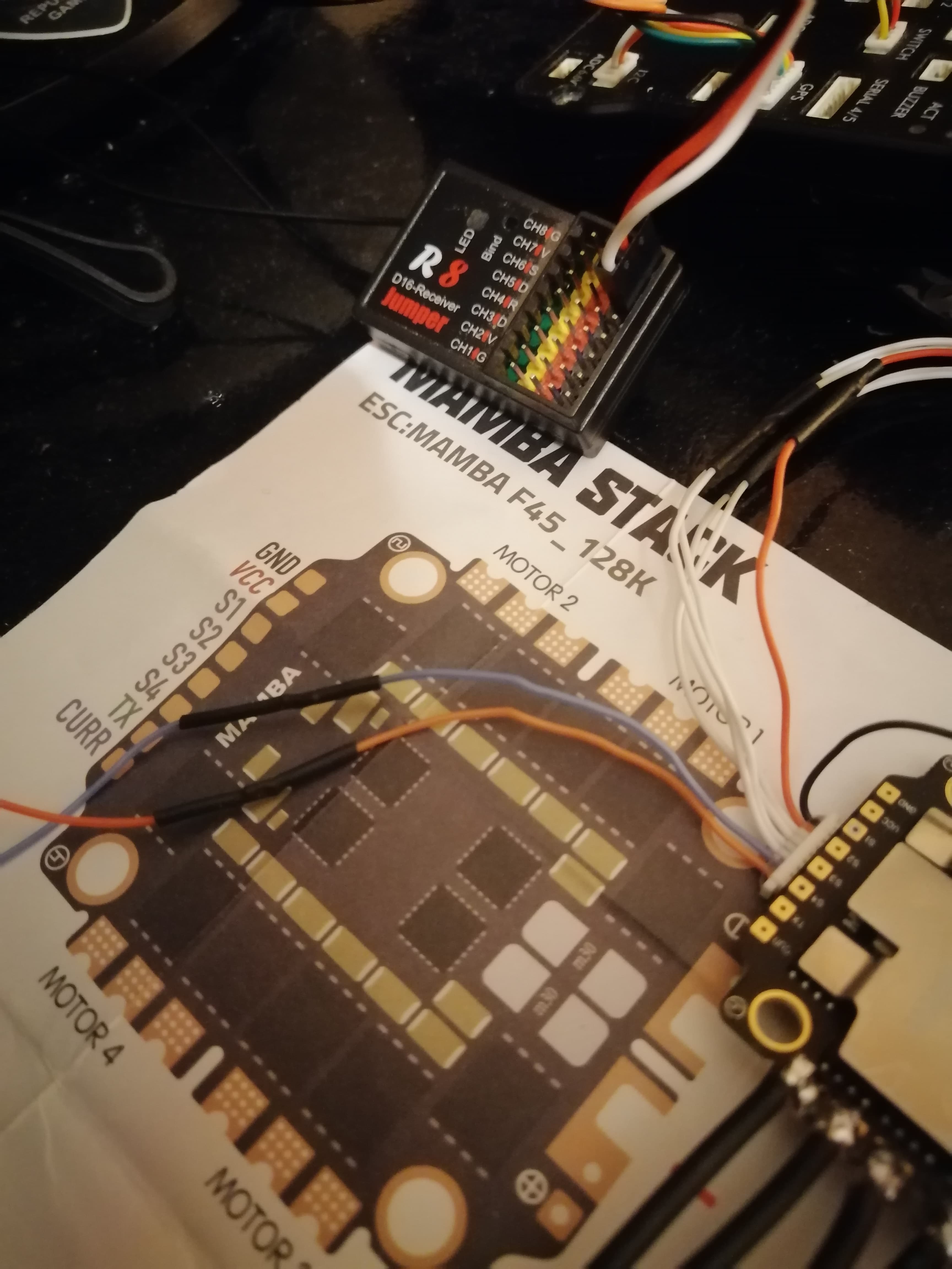
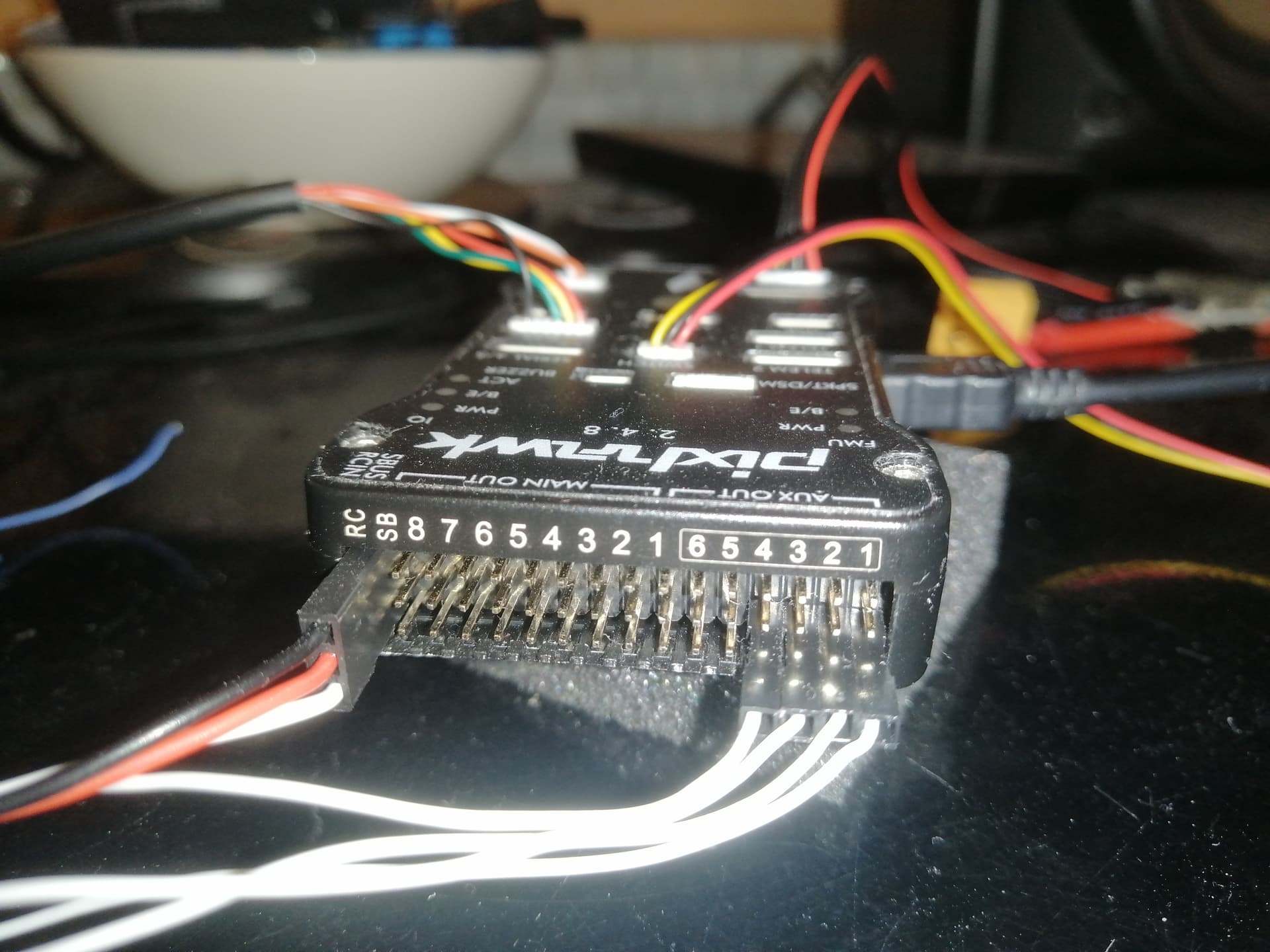
The connection for all 4in1’s to Pixhawk’s is about the same. Connect the FMU outputs (for Dshot protocol) from the Flight Controller to the signal inputs (S1-S4) and ground of the ESC. If the ESC has a Telemetry pin connect that to a serial port Rx pin on the Pixhawk and configure that serial port for ESC telemetry. Most 4in1’s are arranged such that with the battery connector facing rearward the motor order is as per Betaflight. So, set the FRAME_TYPE to 12 for BetaflifghtX. When you run Motor Test in Mission Planner you will confirm if the Motor Order is correct. If it’s not re-assign the Servo outputs until they are.
No. For Dshot you need to use the Aux outputs. 1-6 are Servo 9-12 in the paramneters file when assigning the outputs. Tx connects to a serial port Rx pin and is configrued for ESC telemetry. It looks like you already have a Power Module supplying current information to ignore the “curr” lead.
Hi dave help me please,
I can’t get aux 1 servo to work. In full parameters set SERVO9_FUNCTION value 58=rcin8 but the servo doesn’t work what can I do?