Using dual PMs (Pixhawk 2.1, Mission Planner)?

Hi,

I dont know where to post this thred (Pixhawk 2 / Mission Planner / ArduCopter 3.5 / …)… anyway…

Setup:

  • Hexacopter with dual 6S-batteries
  • Two AttoPilot 180A PMs
  • HexAero Pixhawk 2.1 (Cube with CarrierBoard)
  • Mission Planner (latest installed, 1.3.52 I think it was)
  • Firmware ArduCopter 3.5.5 loaded (latest)

Question: (before I solder it all) Can I connect each battery to their own Attopilot. And connect both PMs to the PDB. And then connect each PMs signals (voltage and current) to each Power-port (1 and 2) on the Pixhawk and monitor them both at the same time in Mission Planner and use failsafe?

Im using an UBEC to power Power Port 1, and havent decided what to power Power Port 2 with yet.

Im after redundancy:

  • If one battery fail, there is another one (failsafe with RTL)
  • If one PM fail, there is another one (failsafe with RTL)
  • If a power-cable / monitoring-cable fails, there is another one (failsafe with RTL)

Is it possible?

/MickeM

I don’t think there is a simple way, but first, do you have reverse current protection, the way you described it if one battery was to fail the other battery would just try to charge it thus you get no redundancy. If the 2 batteries are paralleled they will have the same voltage so there is no use for 2 voltage sensors, what you do get from 2 power modules is more current and power redundancy.

So in your current setup, assuming you don’t have reverse current protection, if one battery was to fail(a cell dies) your drone would just fall from the sky because the good battery would use all it’s current to charge the other battery until a current sensor overheats and explodes. I wouldn’t worry about it tho, as that is not something that just happens, what is possible is that a battery disconnects itself, in such case both your PM’s would still be returning the voltage just one PM would say that there is 0A current(being that there is noise it woudn’t even say 0A). All that means is that it is hard for the autopilot to say “ah, I lost a battery, better go home”.

That is where smart batteries come into play, but being that there are so few on the market right now and that even less people use them, ardupilot doesn’t do much with the data.

Now, what you can do is make your own redundancy checker with an arduino or similar.

First, you need an arduino with analog inputs, we connect the current sense line to the arduino as well as the autopilot.
You can use high power diodes for reverse current protection.
Now you connect all that up and check the current’s on both analog inputs. When the drone is in flight both power modules should show close to same current, but if one battery fails or a cable disconnects one of the power modules should show no current, you can then check on the arduino if the other power module is sending out a lot more current, and if so you change flight mode to rtl with a serial message to the autopilot. That would cost you probably around 50-100$ depending on the diodes you use and comes with a large downside of a diode voltage drop.

Another way would be to use relays or mosfets and trigger them with an arduino depending on the current direction although I don’t know how you’d do that.

I have a close to same setup with one major difference(more batteries):

  • Pixhawk 2.1
  • 6x 4.5Ah 6S batteries
  • Hexacopter with 22" props
  • 2x MAUCH 200A + 5v modules

besides the 2 power modules I have another 5V line for the servo rail

And I just added automotive 100A fuses to each battery but that approach wouldn’t work for you as you have 2 batteries total , you will blow your good battery fuse before you blow the dead battery fuse.
In my case, if a battery cell was to fail all the other batteries would try to charge it up causing it to have high current going in and blowing the fuse, the load would be spread to multiple batteries causing them to have at most 25A more current for a very short period of time. And if one battery fails I just don’t care and continue with my flight. This was more of a protection in case I plug in an low voltage battery among the full ones.

I would say you have no need to worry as that is very slim chance it would be necessary unless there is a mechanical fault(something pierces the battery(bullet, another drone), if that happen’s you’re already going down anyway.

Best of luck

Very long and very good answer! =)

Reverse Current protection…nope! Dont have.

Would work if I have high power diodes on each side (between PM and PDB). But I can not be the first using double LiPo’s, but maybe all uses a simple Y-cable? Thats not redundant. But if one LiPo looses a cell when using high power diodes, what happens if there is 5S from one and 6S from the other to the PDB?

I dont know if the AttoPilot 180A uses any protection backwards.

As you say, not that common that a bigger good LiPo gives up during flying.

You used 6 batteries to avoid the high current? Thats smart. And the fuses.

The easiest way for me is to use a Y-cable and one PM?
The second easiest way is to use your way?

Question… how do you use two PM on yours?

2 batts - 2 power modules …each feeding on of the two power inputs to ONE PH, batts in parallel AFTER the power modules feeding the ESCs etc. is the norm lets you monitor two batts and feed to power ports on one PH

the above scenario but with 1 each batt module feeding seperate PH then feeding the ESCs as above works but will not be redundant powering the PH’s

BUT there is nothing stopping you from paralleling the power feeds to the PH power sockets with just the sense lines going to sperate PHs but again no redundancy…diodes to isolate each batt feed to the two separate PH…but you’d be below the optimal V+ to feed the PH…

ptegler

I am doing this now with the dual battery-setup (parallell):

MAIN POWER TO ESCs:
Power from Battery 1 -> AttoPilot 1 -> PDB -> ESCs
Power from Battery 2 -> AttoPilot 2 -> PDB -> ESCs

VOLTAGE AND CURRENT-SENSING:
Signal from AttoPilot 1 -> Power1-port on Pixhawk2.1
Signal from AttoPilot 2 -> Power2-port on Pixhawk2.1

POWER TO PIXHAWK2.1:
Power from PDB -> UBEC 1 -> Power1-port on Pixhawk2.1
Power from small LiPo -> UBEC 2 - > Power2-port on Pixhawk2.1

(Mauch have a nice solution for the above.)

Question 1: this diode/these diodes… where do I need them? And what sort of diodes?
Question 2: Do I need big diodes between the AttoPilots OUTputs and the PDB? Or can the AttoPilot handle that I connect a battery before the other. Power is going into the others AttoPilots Output.

The above give redundancy for powering the Pixhawk 2.1.
But if one main battery fails (one of the to 6S 10000mAh), the multcopter probably crashes. I would need more batterys (fused) or an electronic device to handle failing battery, I guess?

Anyone knows if the AttoPilot 180A can handle another exactly similar LiPo connected through another AttoPilot to the same PDB?

LiPo 1 -> AttoPilot 1 -> PDB
LiPo 2 -> AttoPilot 2 -> same PDB as above.

The power from one LiPo goes through its AttoPilot and to the PDB, back to the other AttoPilots outputs. Is it protected?

We went for Mauch instead. Have to find out which components to use. PL seems to be aimed for Pixhawk 2-series. Ordering as soon as Mauch answers or we find which components ca be used for the plane and different multicopters.

Hello again!

We went for the Mauch Hub for double LiPo-monitoring.
Really good quality on these stuff! But…
I have a question about the Alarm buzzer/LED.

All the Mauch-components are in place and it all works:
1x Mauch 015 – PL-2-6s BEC 1 x 5.35V with CFK enclosure
1x Mauch 083 – 2-6s backup BEC for Pixhawk 2 - t
1x Mauch 010 – PL Sensor Hub X2-V2 with CFK enclosure
2x Mauch 003 – PL-200 Sensor Board with CFK enclosure – 10AWG

The Hub: https://www.mauch-electronic.com/pl-sensor-hub-x2-v2
And the schematics: https://mediaprocessor.websimages.com/width/1077/crop/53,78,940x596/www.mauch-electronic.com/X2-V2%20with%202x%20PL-xxx-1.png

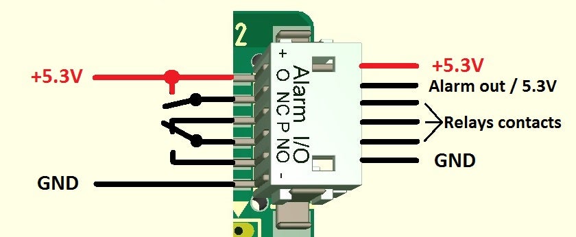
The question: The hole point with the hub is to get an alarm if something is wrong. On the schematics above, there is an alarm buzzer/LED. There is nothing said about this on the page or in any manuals. The pinout on the Alarm Relay-port says: NO, P and NC. NC used to stand for Not Connected? But how and what do I connect to this port? The cable was in the package. I have emailed them and also filled in their forms for support. Nothing. :frowning:

NC is normally closed, which will equate to "batteries are good"
NO is normally open, contacts will close when batteries go bad
P will be the common terminal, so you might connect some power supply or 0v, depending on how you wire up an external device such as a buzzer.

OK, so it is meant that I could put the LEDs power-cable to P and out through NO to the LED?

I also have another word-problem with Mauch… what does Solder IN and Solder OUT means regarding a “jumper”? Is it connect/dicsonnect, short/cut, solder/not solder, on/off? Look at photo and text under “Voltage selection”: https://www.mauch-electronic.com/pl-xxx-sensor-boards

The HS-version is more explainable… There is P, NO and NC.

Anyone else using the Mauch PL-Sensor Hub X2 V2?

The Mauch PL-200A-sensors is delivered with the values from the test result for Voltage Divider and ampere per volts, for each sensor.

But what to do if I am using the Hub? Should I use mean values of the Voltage Divider and the ampere per volts-value?

Another thing…

When using only 6S-batteries, the sensors have a “jumper” that should be soldered to use up to 7S-batteries. Without the solder, it can be used for up to 20S-batteries.

But, when reading what to do if you solder or not (choose up to 7S or more), then I get confused…

[i]"First select the correct voltage measurement range according your used main battery.

Solder bridge out = Up to 20S (max. 85V)
Please use the voltage divider from the final test result (approx. 26.8)

Solder bridge in = Up to 7S (max. 33V)
Please use an voltage divider of 10.0 -> The measurement will be quite accurate. However, you can always measure the main battery voltage with an DVM and readjust if necessary.[/i]

If I solder, then I should use a divider of 10 and get a “quite accureate” measurement, but can adjust it if necessary. This is why I skipped AttoPilot 180A, to leave the “quite accurate” that was hard to get near to useful. Should I solder or not? It is a pain in the a-- to get to the sensors… :-/

We didnt rip the hexacopter apart to solder those pads on both the 200A-sensors, it works very well as is.
Dont know if I am gonna solder those pads on the new octacopters two sensors either, maybe try to see the difference.

If I want to get deeper on this, I guess it is Mauch I have to get some answers from and put them here.

The alarm works great. =) I didnt use powerful LEDs or loud speakers. I connected the external voltage module for the Futaba-receiver by this alarm-relay on the sensor hub and the Futaba transmitter is alarming when the relay disconnects the power to the external measurement.