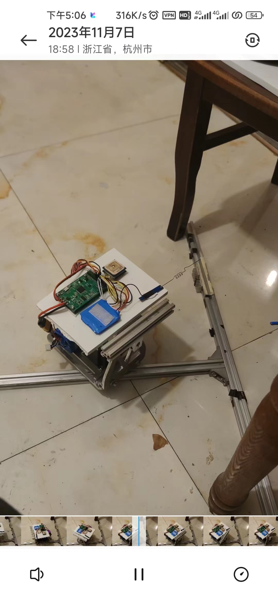
Using a stepper motor as the driving force for rotation is theoretically much more stable than a servo. However, in actual use, since the software is not optimized too much, it cannot achieve a very smooth rotation effect. I made my own PWM to pulse signal control board. There are several points that need to be optimized in this process. First, the accuracy of the PWM signal is not high. It can only be accurate to about 1US. If it is converted into a circle of 360 degrees, there will be almost a virtual position of about 0.3 degrees. The microcontroller reads the pwm. The signal won’t be completely accurate, which can cause clicks to jitter even when stopped. For this, I set a certain virtual bit on the software to prevent jittering back and forth. Because a virtual position of about 1 degree is set, when tracking the aircraft, the antenna will definitely cause errors with the actual aircraft position, and the antenna will always lag behind the aircraft. The way to solve this problem is to add feedforward to PID. Obviously I didn’t find the adjustable item for FF in the software. Of course, this can be added to the PWM-to-pulse microcontroller. The last point is that the PWM frequency output by the firmware is very low, which causes the motor to always move when it rotates. I tried to set the acceleration and deceleration of the motor to very low, which will play a certain role, but this also This will cause the antenna to be unable to catch up with the aircraft when it is at close range. The video below is the first test video, the wires are a bit messy, please don’t mind ![]()
https://www.youtube.com/shorts/h58MUWv6-Lg
https://www.youtube.com/watch?v=-ngJBDiDaZk