I’ve been waiting for this feature for a long time. I think it is very important that ardupilot has this kind of features. I’m thinking about buy my simpleRTK2B+heading.
I would like to ask. still with some bugs, It is functional, Is flyable?
I’ve been waiting for this feature for a long time. I think it is very important that ardupilot has this kind of features. I’m thinking about buy my simpleRTK2B+heading.
I would like to ask. still with some bugs, It is functional, Is flyable?
Hi there, what did you mean by “solved”? I am even newer as I just joined today. I am seeking to use dual-antenna gps to be the source of Yaw. Could you tell me some details how did you solve it?
There is a PR that fixes an GPS baseline YAW issue. Unless you understand that sentence, and can compile the code from source you will need to wait for a stable release.
I mean “Solved” because I have found myself the way to get the “dataflash”. At that time, when I was super new to the Ardupilot, I had some confusions on terminology and definition, and @jimovonz reply
a “useful” link for more confusions, I am sorry to say but this did not help for newbie!
@dacheng, In case of using dual GPS with F9P, I think it is challenged to try because theoretically, It should work but I have not seen any successful cases. If you still want to try, I suggest you to be familiar with F9P configuration first and after that, hooking up 2 of them to the Ardupilot. For more convenient way, you can contact Ardusimple for using their product and request the samples codes!
I did a test of YAW from GPS just now. I use a dual-antenna GPS unit which supports GPHDT sentence. I have all compasses disabled, use EK3. I believe the only YAW source is the GPHDT and assisted by IMU. But what is strange is that sometimes the variance between YAW shown in MP and the output of serial data terminal can reach up to 20 degrees and sometimes quite close. I understand there can be some reasonable tiny variance because of EKF processing. But 20 degree seems too big. Anyone has ideas?
This is the screen record video: https://youtu.be/BVsolHgprms
Hi , do you use tersus GNSS on copter ?
I cant stable hover with tersus gnss : Flies hover by circling a 2-3 meter diameter circle in RTKFixed
Now get a better alignment of YAW and GPHDT by adjusting GYRO_P_NSE = 0.1 maximum.
https://youtu.be/XM9MQ-NIRJ8
@dacheng GPHDT is from NMEA, right? Does Ardupilot allow using sentences from NMEA and UBX at the same time? Your case, I guess you did not use the NMEA only, am I right?
Yes, GPHDT is from NMEA. I think Ardupilot does allow NMEA and UBX at the same time because you can set GPS_TYPE and GPS_TYPE2 different to be NMEA or UBX.
But in my case, I only have one GPS unit, a dual-antenna unit Tersus BX316D. And I have no compass. So the only YAW source is GPHDT from NMEA.
Nice, just curious that does the BX316D use modified NMEA? As far as I know, the original NMEA just allows 12 maximum satellites count (for displaying in Mission Planner), right?
I think the BX316D just uses the standard NMEA-0183. And I do not know there is such a limit. I often see 16 satellites in MP when using GPHDT for YAW.
Good day All
I am wondering if there is any progress on this feature with the latest FW 4.0.4 rc2 ?
I am trying with the ardusimple Rtk HEADING setup and configuring as per the wiki:
https://ardupilot.org/copter/docs/common-gps-for-yaw.html
I am not having success and am wondering if this wiki page applies to the ardusimple board?
Are there other steps that I must take to get the heading working?
Must I connect both boards’ UART1 to the cube?
Thanks!
AFAIK you need to use FW 4.1.0-dev a.k.a. git master to do that.
Thanks Amilcarlucas. I am just going off what I read in the wiki.
It seems that the functionallity is present in 4.0.4.
But full functionality of having the option of a Mag fall back is only in 4.1.0
Has anyone got this system working with the 4.0.4?
Thanks!
This topic is really interesting to me!
I’m new to ardupilot and I’m trying to bring up my first system based on pixhawk to make my ground rover move autonomously.
I have two GPS ZED f9p from ublox that can work in RTK and I would like to use them with dual antenna configuration since the heading is very critical for me application.
I also have a dual antenna receiver from Novatel which provides a 0.1° of accuracy with a base line of 2 meters.
If the dual antenna heading supported on the newest firmware of ardupilot? If yes, how is it working?
Should I use pixhawk 4 or should it work on any version?
Thank you!
It works well. Configure ArduRover as described here
You can read some of the trials and tribulations of some of us who initially had trouble but eventually got it all to work starting around post 107 of KevinG’s Autonomous zero-point turn Lawn Mower - Blog - ArduPilot Discourse
Thank you! I’ll check them immediately!
I followed the instructions suggested by @ktrussell and I set these values:
- SERIAL4_PROTOCOL = 5 (“GPS”) assuming the 2nd GPS is connected to serial port 4
- GPS_TYPE = 17 (“UBlox moving baseline base”)
- GPS_TYPE2 = 18 (“UBlox moving baseline rover”)
- Set the GPS_POS1_X/Y/Z and GPS_POS2_X/Y/Z parameters for the GPSs (see Sensor Position Offset are here)
- GPS_AUTO_SWITCH = 1
- AHRS_EKF_TYPE = 3 (to use EKF3)
- EK2_ENABLE = 0 (to disable EKF2)
- EK3_ENABLE = 1 (to enable EKF3)
- EK3_MAG_CAL = 5 (“Use external yaw sensor”)
- EK3_MAG_CAL is not used for this feature so it can be left at its default value (“0” for Plane, “3” for Copter, “2” for Rover)
- EK3_SRC1_YAW = 2 (“GPS”) or 3 (“GPS with Compass Fallback”)
on Mission Planner and I wrote them to my Pixhawk 5X.
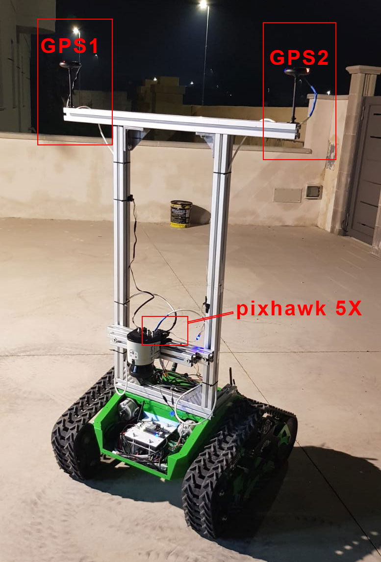
This is my current configuration:
The distance between both GPS modules is 0.90 m.
I’m using this kit from Holybro and so I have 2 x H-RTK F9P rover modules and 1 x F9P base station, so all the modules run on ublox chips.
I tested the configuration without the RTK corrections and the heading seems to be fine and I’m able to make the vehicle move towards the GPS waypoint (even if there are some errors since the GPS signal isn’t very well).
Now, I would like to use the RTK corrections in order to improve the positioning and the heading information.
Following this document: CubePilot Here+ RTK GPS — Copter documentation I can understand that I can use Mission Planner to inject the RTCM3 corrections from the base to the first GPS module connected to GPS1 connector.
But, what I have to do in order to inject also the RTCM3 corrections to the second GPS modules?
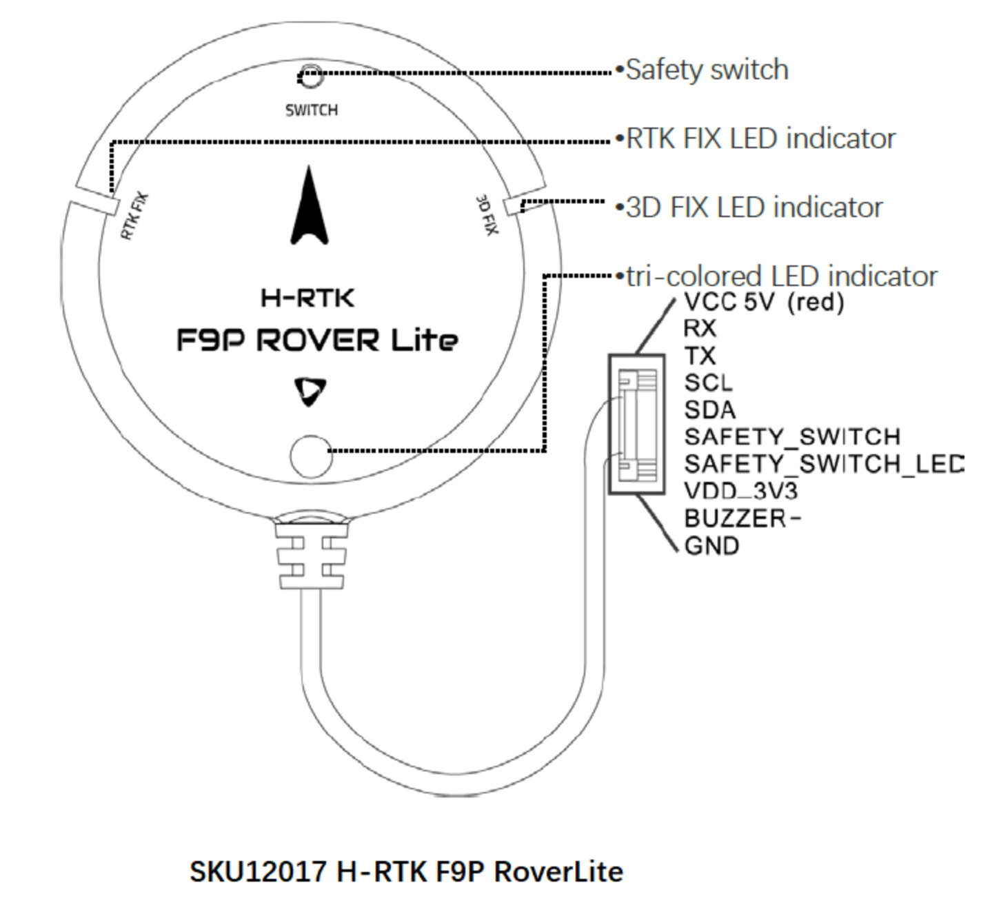
I see that you directly connect both rover modules on UART2, the problem is that my GPS modules use a JST 1.25 10-pin connector and this is the pinout:
I connected the first GPS to GPS1 and the second on the 6-pin connector named GPS2 on my pixhawk 5X.
I think the module doesn’t have an additional UART interface so I do not know how to make enable the communication between them. May be I can use SDA and SCL and enable the RTCM3 messages IN and OUT on I2C under u-center? Are these two pins used by pixhawk or does the GPS port on pixhawk only use the RX and TX pins?
Is there another way to inject RTCM3 corrections from the base station directly to the second GPS by using mission planner?
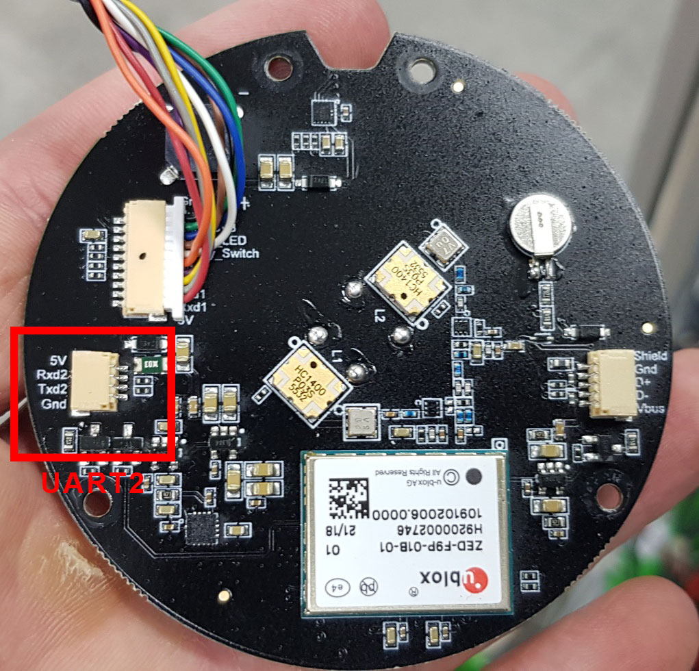
Today, I disassembled my modules and I’ve found out that, fortunately, there is a connector for the UART2 on both the modules!
So, I can wire both modules by using their UART2 as @Vincent_Miceli and @Yuri_Rage did .
GPS1 RX → TX GPS2
GPS1 TX → RX GPS2
GPS1 GND → GND GPS2
In this way, should I set with u-center:
RTCM3 as protocol IN and OUT on GPS1 on UART2
RTCM3 as protocol IN on GPS2 on UART2
and enable these messages: 1005,1074,1084,1094,1124,1230 on UART2 ?.
Then, I should inject the RTCM3 messages from the base station to the first GPS1.
Is it everything correct?
What kind of baud rate should I set for UART2?
Set 230400 or 460800