The default configuration is AETR, so if you’re using a different setup then you’ll have to adjust. No big deal. RCMAP is for that.
Mine is a quad copter so it would be RPTY. It is late, my brain is fried so I will continue manana. Thanks
RPTY / AETR, same same. Most of the brands that sell gear (even to quad and heli pilots) will still reference AETR. Likewise if you’re setting up radios in EdgeTX or OpenTX, they will reference the sticks as Aileron, Elevator, etc.
Allister, I thought I understood this but I guess I haven’t. I have attached a diagram showing what I have. Correct me where I am wrong…
I am using the X configuration. From this I assume that servo 1 controls the motor labeled 1 in the top right corner of the X diagram, likewise I assume that servo 2 controls the motor in the bottom left corner of the diagram, servo 3 controls the motor in the top left corner of the X diagram, and finally servo 4 controls the motor in the bottom right corner.
I connected my FC to my ESC pin to pin, i.e. 1 to 1, 2 20 2, V to V, G to G, etc. Therefore I assume that I now have M1, M2, M3, and M4 being controled by the ESC.
The right diagram shows my layout, i.e. where the motors are mounted on my frame. The motor numbers on my frame do not correspond to the same motor numbers on the X diagram.
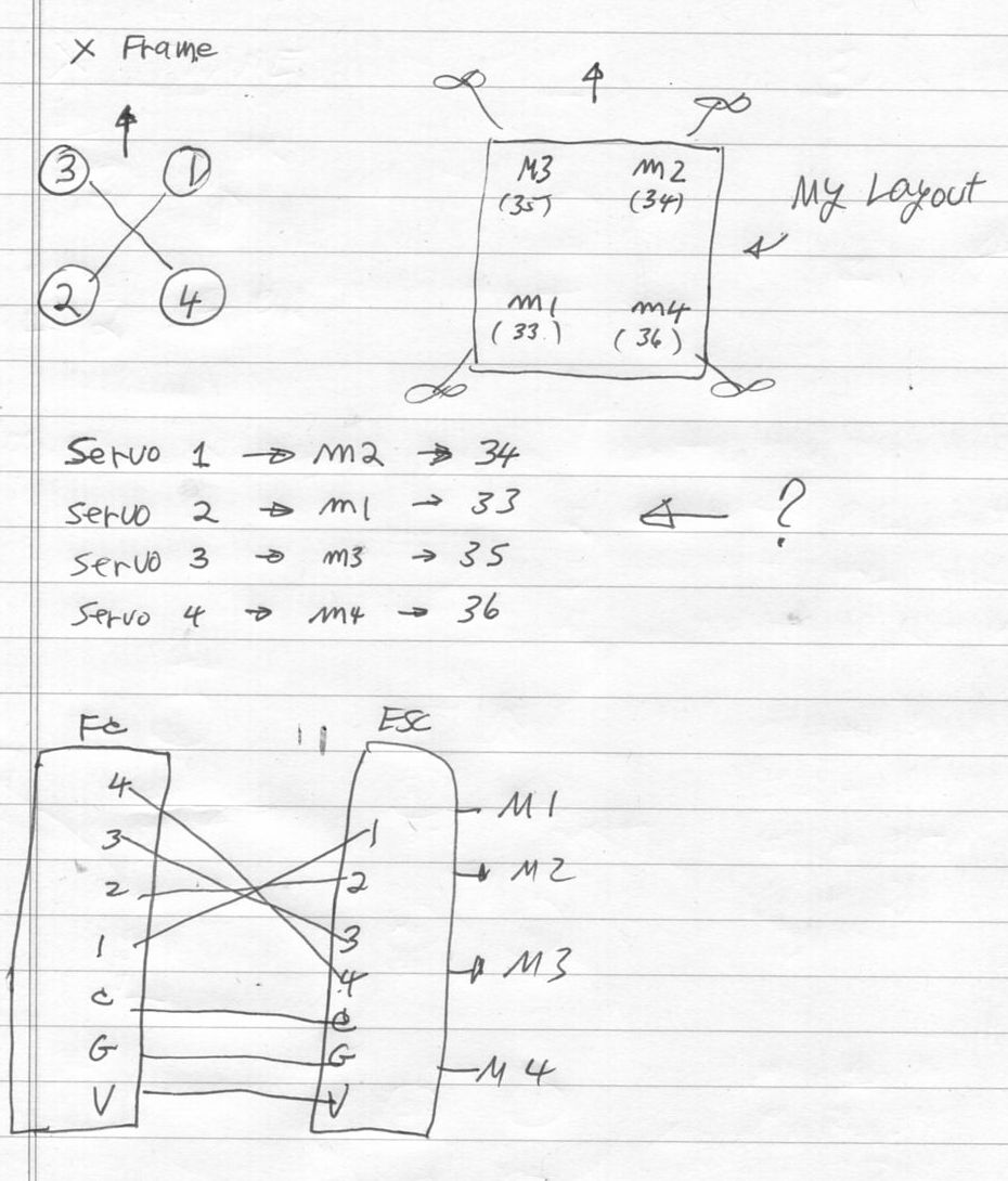
From this, I would assume that servo 1 would control M2, servo 2 would control m1, servo 3 would controlm3, and servo 4 would control m4.
If this is the case then I would think I should have the servo 1 parameter set to 34, servo 2 parameter set to 33 , servo 3 parameter set to 35 , and servo 4 parameter set to 36 .
Is this correct? I really appreciate your help. I am gradually learning about all of this but still a learner at this time.
PS. I should add with this config and doing a motor test, Motor A is top right, Motor b is top left, mitor c is bottom right, and motor d is bottom left. Is this corect???
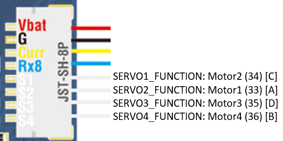
I think you want this, if I’m reading your wiring correctly (seems to match what you deduced):
SERVO1_FUNCTION: 34
SERVO2_FUNCTION: 33
SERVO3_FUNCTION: 35
SERVO4_FUNCTION: 36
On the autopilot itself, the S1-S4 labeled pins should correspond to the SERVO1-SERVO4 outputs, in order.
Graphically, like this:
Well, I thought my/your lineup would work but the stick movements do not match the motor rotations. In addition If I put the throttle at idle and do a pitch down, tip the front down, I woujld expect that motors 2 and 3 would respond. This is not the case. I et motors 2 and 1 for example. The same thing happens to my stick movements. I thought I coujld modify the RCMAP but hae not been able to fix everything as yet. Puzzling.
Also, when doing a motor test, does button A correspond to motor 1, button B correspond to motor 2, and etc. Does not seem to be the case. I am totally confused.
Wire it up as @Yuri_Rage has suggested.
Testing motor function on the ground without the drone flying is pointless. Don’t do it. The control loop does not get the response it’s expecting and you won’t see results that make sense.
Check the HUD/horizon display on Mission Planner. Does it move correctly when you move the drone.
Check the motors with the motor test. If you read the links we sent you yesterday, you’d see that that motor A = Motor 1. Motor B = Motor 4. Motor C = Motor 2. Motor D = Motor 3. Yes, it’s confusing. There’s lots of posts here explaining why.
Check the RC inputs on Mission Planner. When you move the pitch stick forward, the bar graph will go down (commanding negative pitch for forward flight). Roll, Yaw, and Throttle should move the way you expect. If one is backwards you can either reverse it in Mission Planner, or on the radio. You decide.
Post the results of your motor test here. In other words, when you push “A,” what motor spins, etc?
Also post a screenshot of your servo setup screen.
DO NOT modify RCMAP parameters based on ground testing motor order with the sticks. As Allister says, it’s a completely invalid test. Only modify RCMAP if you do not get expected results on the Radio Calibration page.
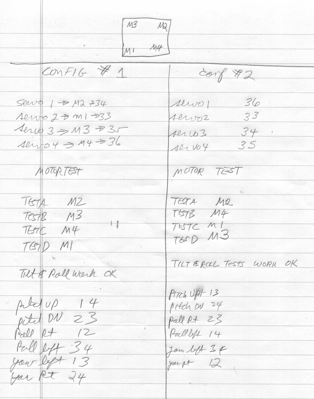
Attached is my latest data. In all cases the HUD seems to owork properly, i.e. pitch and roll are indicated correct.
I tested using two sets of parameters. #2 is the set I received yesterday, and #1 is what I thought should work. You are correct in that trying to test the functions moving the sticks when armed (forced arm) sometimes causes strange results but in general I think I have good data. I show in both cases what motors move when the sticks move. Also I have done the motor testa,b,c,and d.
In my first diagram I showed that the connections between my FC and ESC are 1 to 1 per the best data I have. I wonder what would happen if the wires were reversed? I actually tried this but did not get good results, only different.
I am confused by all of this. I thought I understood it but I guess not.
I think what’s messing you up is that you have M2 and M1 reversed. But if the front right motor spins when you test motor A, that’s all that matters. - don’t change anything if it’s working. Don’t get caught up in the labels.
Next, make sure the motors are spinning in the correct directions. Refer to the charts in the links we sent for directions. “Props-in” if you’re familiar with the term.
Again, don’t bother with force arm and seeing what motors move. Sure it can be fun, but it’s not telling you anything and probably just confusing things.
Not very helpful. Physically, which motor spins when you push “A” with the current set of parameters?
In other words, I want to see something like this, where the letter corresponds to the physical location of the motor that spins when you mash the button.
C A
D B
And then I want a screenshot like this (of the config that resulted in whatever motor order you got during the test):
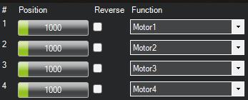
(on Windows, use Win+Shift+S to take a screenshot)
The way you have things labeled makes it very unclear as to what’s assigned where. We can avoid rewiring if we can just see the info requested here.
Once we have that much, we can attack motor direction.
All motors are spinning in the correct direction.
What do you mean about M2 and M1 reversed. M1, M2,M3,and M4 are printed on my ESC…
So what parameters in which config should I swap and test??
Very puzzling.
The labels on the ESC are inconsequential because we don’t know where you have them wired. You’re using “M1” to denote both an ESC label and an output function, and it’s simply confusing all of us. See my post above, and we will sort it out.
Forget what’s on the ESC.
When you test Motor A, which motor moves? It should be the front right. B, C, D then go around in a clock wise circle. Doesn’t matter what label is on the ESC. It’s all configurable so they could have just as easily called them red green blue and yellow.
My latest attachment shows what motors turn when the buttons A,B,C, and D are pushed for both configurations. They are called TestA, TestB, TesstC, and Test D
But I can’t decipher it properly. If you want help, please reply with the info requested. Allister just asked the same.
1 Like
Two choices:
1 - Since you aren’t using the same numbering as we’ve been describing, verify yourself that the motors are working per the wiki: Connect ESCs and Motors — Copter documentation
2 - Go to a safe place without anyone around and just send it. make sure you get video.
Attached is the info requested
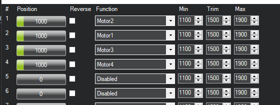 This is for conf 1
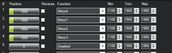
this is for conf 2
I think my wiring is correct. I have it on my first atteachment
FC M1 → Esc M1 → M1 on the physical esc. esc.
Ok, we are halfway there. Now, for Config 1 (and only Config 1), please post something like this, indicating your motor test results (i.e., physically, which motor spins when you push each button?):
A: Forward Right
B: Back Right
C: Back Left
D: Forward Left
A M2 Forward right
B M3 forward left
C M4 Bottom right
D M1 Bottom left