I am trying to understand the interface between the FC and this particular ESC. The diagran above says “current” . Now really, what does that mean? Do you think the FC is supplying 40A of current through this wire? Of course not. What does "current " mean and why is it connected to the Transmitter pin of serial port 8, i.e why is current connected to Tx8? Does the FC sent a “current” command to the ESC? I have no idea and would like to know.
The current pin from an ESC, all ESC’s, is a voltage equivalent signal from the current shunt resistor and it does NOT go to a serial port it goes to a current input pin which that Flight Controller has.
I think you need to review the available docs for that ESC and the Matek H743-Slim (right on their website, ardupilot mapping) as you are confusing several different things here.
You do now understand there is no telemetry from that ESC so any question about serial ports is meaningless in this context right?
You should:
Flash Bluejay to that ESC
Flash the Bdshot version of firmware to the FC
Connect 7 wires from the ESC to the FC none of which go to a serial port.
Well, I would rather not get into flashing BlueJay into the ESC and changing the version of Ardupilot to the Bdshot version at this time. Maybe later.
As I have read, Ardupilot will do Dshot (not bdshot) as it is, right ?
I am proud of myself that I flashed the “normal” version of Ardupilot inot the H743 with no issues. I am not looking for trouble.
You stated…“Connect 7 wires from the ESC to the FC none of which go to a serial port.” There are seven wires. However, the one marked “current” goes to Tx8 on the FC. Tx8 is normally a serial port. Perhaps it is changed to an ADC input.
No it doesn’t. It goes to the Pin marked “Cur”. There are actually 2 Current input pins on these FC’s. If you read the Ardupilot Mapping page I suggested you would see this. This pin is also available on the 8 pin connector.
On the plus side if you did make that mistake it would not smoke the serial port as the current signal is an analog voltage of 3.3VDC max. Analog voltage, not serial data…
Well, I guess you are partially correct. If I list the pins on the FC connector they go as
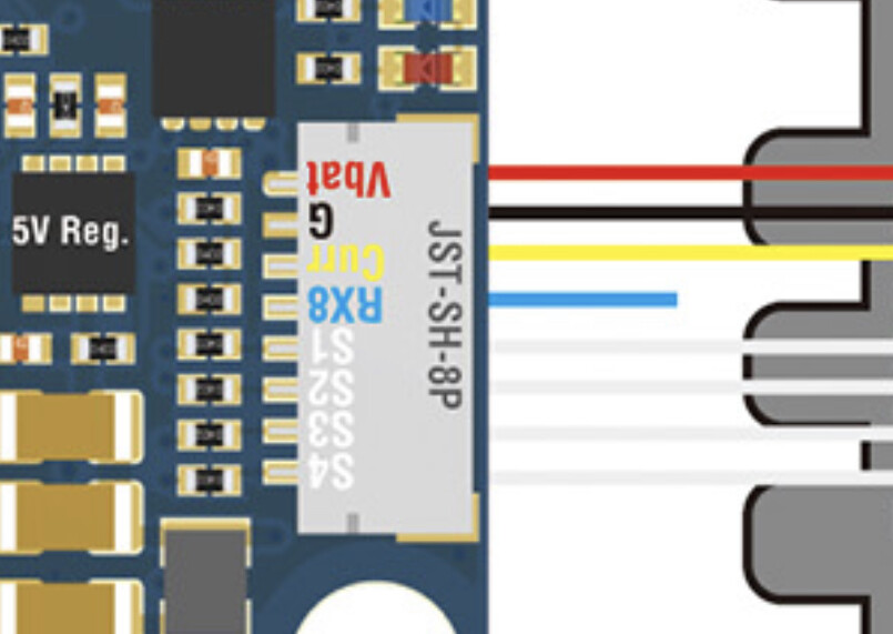
Vbat red
G b black
Tx8 yellow
Rx8 blue stub
Cur ??
S1 white
S2 white
s3 white
s4 white
When the yellow wire goes through the connector it might go to the “Cur” but it looks like it goes to the Tx8 pad. I will get my trusty mhometer and check it out.
Things are looking much clearer. I will solder to the “cur” pin.
You are absolutely correct. I did not have as good of picture.
Problem solved.
Thanks Dave.