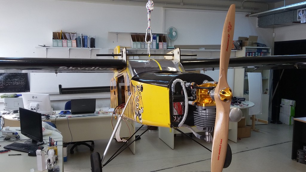
One thing that everyone was warning us about when we settled on an Internal Combustion (IC) engine, was vibration. Vibration will be plenty, vibration will be large, vibration will swamp your sensors, vibration will tear your plane apart. Okay, I may have overreacted a bit there, but only a bit.
Firewall
So, first of all, we wanted to reinforce the whole fuselage front section structurally, to prevent shears and craks from appearing.
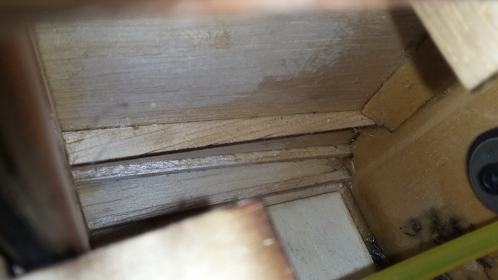
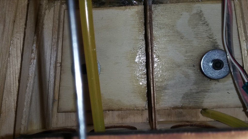
We poured thin CA glue inside all of the wooden seams, along all wooden beams of the front section. We can never be sure of the manufacturing rigour of consumer products.
Afterwards, we continued with reinforcing the firewall. We applied 30’ epoxy glue, thinned with alcohol over the inside of the firewall. Then we applied two glass-fiber cloth layers over the glue and re-applied glue over it. It was a messy procedure and the hardest part was to keep the cloth relatively wrinkle-free over the angles and ribs, while applying the glue with a brush.
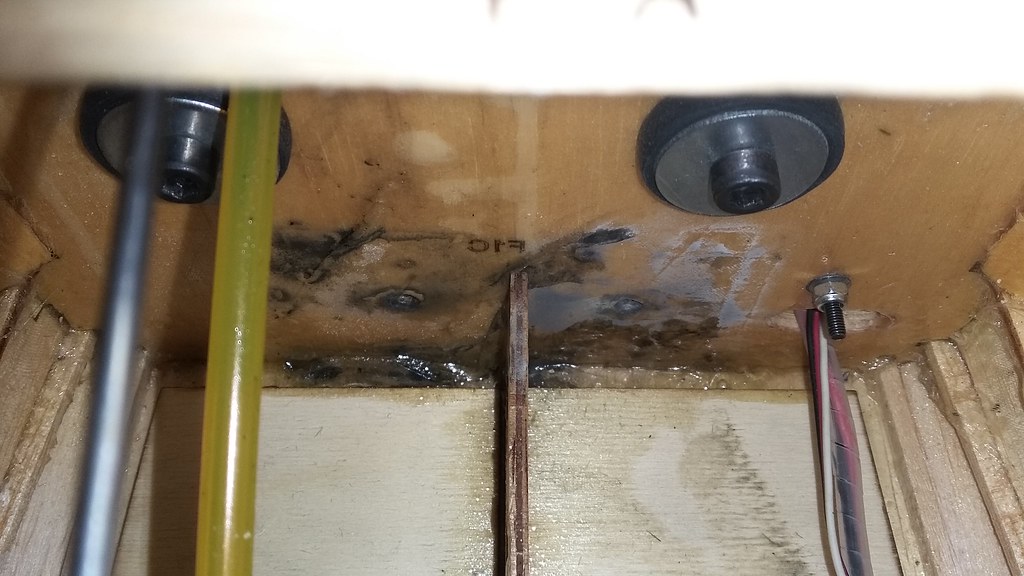
We let the whole thing dry overnight and did the same thing for the front of the firewall, but this time with one layer of glass-fiber and one layer carbon-fibre cloth. We hope that it will divert some of the EMI from the electronic ignition away from the electronics placed inside the fuselage, but we can’t be sure until we do some RF tests.
Vibration Damping
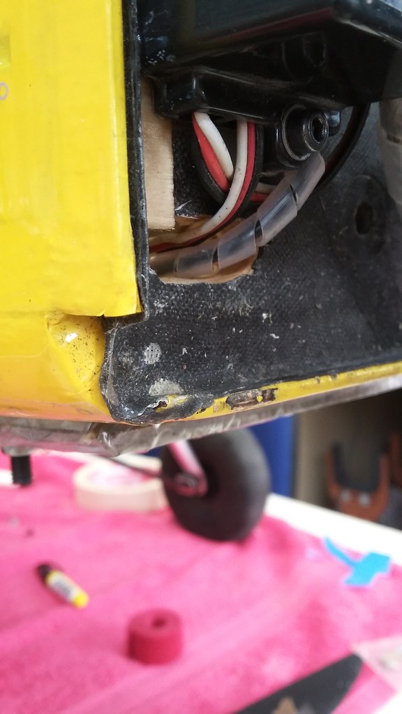
That took care of solidifying the aircraft front section, but we wanted to have some extra vibration isolation between the motor and the fuselage. We ordered some aftermarket anti-vibration motor mounts from SDSHobby and drilled the firewall to the correct points (follow the engine manufacturer’s pattern!). We inserted the rubber pads and tightened the motor mount screws around them.
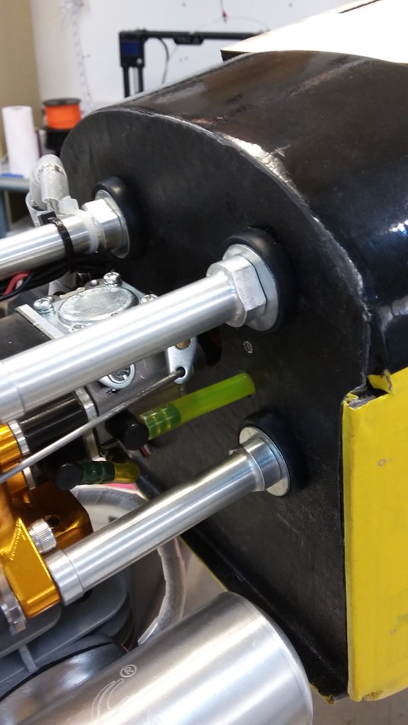
An important question rose at this point: How tight should we fasten these screws? Supposedly, depending on the eigenfrequencies of each system, the screws should be tightened by varying amounts. What that means exactly is open to interpretation.
We were not able to perform a frequency sweep against the number of turns of the screws. It’s very hard to tighten the motor mount while the engine is running and turning the propeller. The general impression is that the less tight the dampeners are, the lower their cutoff frequency is, without any hard facts given.
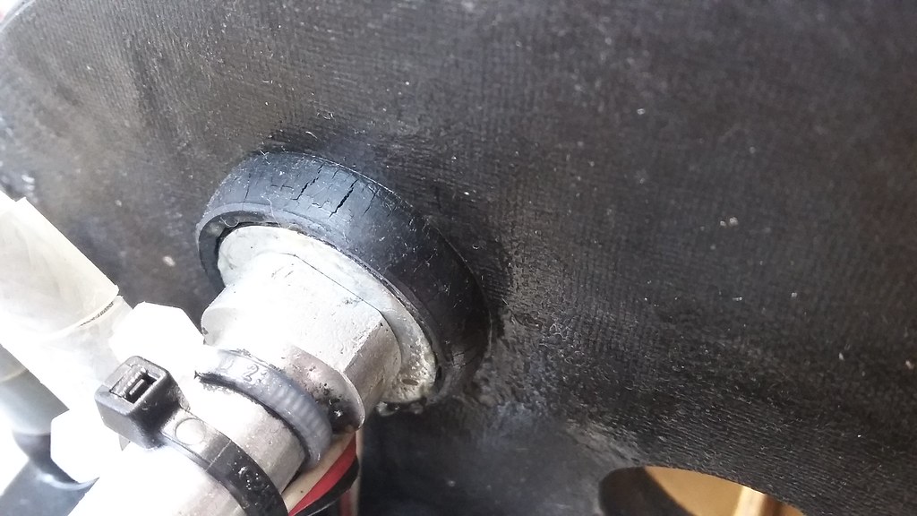
The dampeners needed some more attention, because after a few months they started to dry up and crack. Covering them with a thin layer of vaseline seemed to halt the degradation.
In general, we are not happy with the overall vibration isolation. The airframe shakes violently on low revs and Pixhawk 1 on its standard foam pads as well. It exhibits marginal vibration readings, especially on the z-axis. Sadly, we currently don’t have any other way to isolate payloads from vibration, except for individual damping.
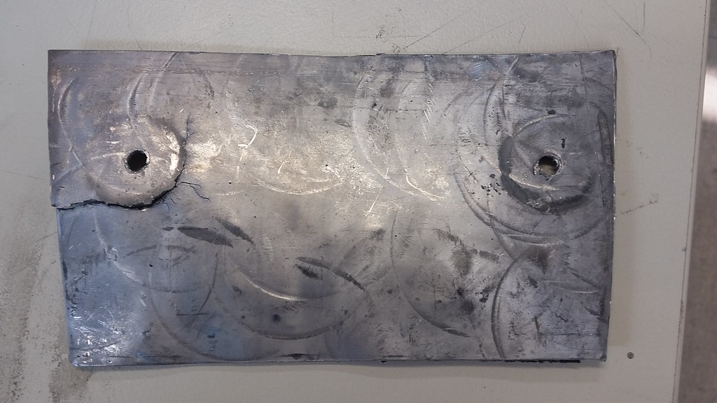
Ballast Bay
It tunred out that we needed a lot of front weight to balance out the aircraft. Why? Well, let’s say that I might have designated a lot of equipment to reside behind the CG. The point is that we needed to add weight in an efficient, compact and adjustable weight. Additionally, the balast should be mounted as far forward as possible, to get the most torque out of each gram.
After one or two iterations, we settled for the configuration show below. The floor of the fuselage front section was drilled and two M5 hex screws were threaded through. We bought lead sheets and cut them to size and shape, so as to fit on the underside. We added as many sheets as needed to balance out the plane and secured them with safety nuts. With this approach, we can add or remove sheets, depending on payload.
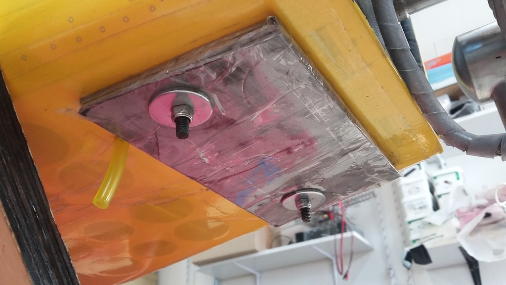
Lead sheets are so soft you can cut them with a pair of scissors, but there is a downside to that. After their first flight day, we noticed that the bottom sheet had cracked, under the vibration coming from the engine. A quick and easy solution was to wrap all sheets together in packing tape and then mount them with the scews, managing to hold them all tight and neat.
This concludes this part of the UnATRaP blog series. If you have comments or recommendations, please let me know. Until next time!
Previous article: Part 1: Selecting the Airframe
Next article: Part 3: Tailwheel and Rudder