@olliw42 following your test code, I will follow-up with a 3 UART node , probably adding the Cheerson Serial Opticalflow
1 Like
thank you for that Patrick great tutorial best to buy parts from jdrone or have you got a link of were to get the parts please
Hello
JDrone sells complete units, for building I suggest you google the parts to find the best supplier on your area. I ordered from Banggood, AliExpress, Ebay and Amazon.
1 Like
Nice tinkering and playground for testing UAVCan. Nice and clear explanation too, Patrick. Thanks for that.
About the whole purpose of this though, I can’t imagine doing this in practice, even on a DIY project, when it involves adding 5 extra electronic boards and extra wiring when the main purpose of UAVCan is supposed to be having simpler builds with fewer parts/wires !
your counting is, frankly, a bit odd. I mean, if you were to replace the pixhawk by modules of its’s individual components (which e.g. Patrick is known to have done, see his linux builds  ) you also would have plenty of wiring and electronic boards, yet you would not put in question the concept of it … so it is here, you can do that with just one electronic board, the UC4H general-purpose board
the full ease of UAVCAN will come to live only once enough UAVCAN specific sensors are available … which it currently is not (except of few) … so one has to chose: either to wait another millenium or to start now with what’s possible
just remind you how the first MultiWii copters looked like …
gladly people didn’t got distracted by such arguments (and gladly people were faster moving than AP on CAN matters)
2 Likes
Thank Hugues,
I agree with you that this setup is a little bit clumsy and I know you know that this is a technology demonstrator.
Please take a look at jDrones nodes , they are pretty neat and they offer some standardized connections and cabling.
I tried to demonstrate that UAVCAN can be used as a viable technology that is affordable and easy to implement, allow me to fine tune my next projects and I am pretty certain you will be interested exploring this technology on one of your build
1 Like
I will take a look at the JDrones nodes and might get convinced 
Just received my UC4H from jDrone http://wiki.jdrones.com/can/gennode , thanks for the fast delivery 

Loaded one GenNode with Notify firmware.
“Show your autopilot status on UAVCAN connected 0.96“ OLED board.”
Loaded the other GenNode with UartBridge and installed 2 x TFMINI.
Please note the large capacitor of 470 uF (actually it is a little oversized , but that’s all I had on the bench) to prevent current surge at startup as the GenNode has a build-in resettable picofuse that is shutting down if inrush current is too much. Bear in mind if you plan to use these type of devices as the TFMINI draws 80mA each nominal (you can double for inrush). Alternatively you can use a separate source of power to feed the node, you then need to connect the supply to the devices directly (there are some external power feed connection options on the Gen Node) and keep common grounds.
Additional notes on the picture above:
- The power supply is an external regulated 2 Amps AC adapter for bench testing.
- The power is not connected to CAN of Pixhawk as we keep the ‘‘exclusivity rule’’ = just on source of supply.
- The pixhawk internal regulator is sharing its output of 2A (nominal 1.5) to all peripherals and I personally would not recommand using it, a dedicated UBEC being best.
- The balance line is terminated both ends : One end to the internal resistor of PixHawk, the other end is a terminator block connected to the SLCAN module.
- All these are in conformance with techniques of Balance Lines Distribution (see below)
Here is a little schematic from TI (http://www.ti.com/lit/an/sloa101b/sloa101b.pdf)
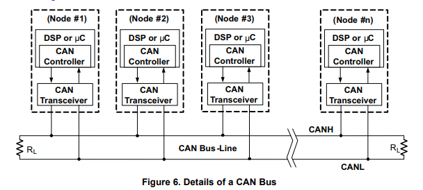
Think of it when you plan your CAN installation:
- Single source of power on the bus (You can use additional power sources to individual nodes)
- Terminator (120 Ohm) at both ends
- Adding some noise immunity if the bus gets over 1 Meter (Shielding or else). The supplied jDrones cables have the CAN Bus Lines twisted.
- The power is not connected to CAN of Pixhawk as we keep the ‘‘exclusivity rule’’ = just on > source of supply.
- The pixhawk internal regulator is sharing its output of 2A (nominal 1.5) to all peripherals and I personally would not recommand using it, a dedicated UBEC being best.
- Single source of power on the bus (You can use additional power sources to individual nodes)
I beg for pardon, but I can’t agree with this as a general recommendation.
I would recommend to not draw too many general recommendations at this early stage of exploration. Practical experience with more nodes than 2 may lead to alternative insight.
![]()
Olli , these rules will not change = The datalines must be balanced and a single source is a general power supply rule.
Do you have reserves on specific issue ?
The datalines must be balanced
I wasn’t commenting on balanced data lines. Even though I here too have my own opinion. ![]() I use it since 1-1/2 years with just one termination resistor, not paying any attention to balancing, and also not paying any attention to daisy-chaining etc … so I’m doing about everything wrong according to CAN textbooks … but I couldn’t yet identify any issue, and it’s clear to me that the moment there I’ll have an issue because of this will never come (one reason btw I use the TJA). So, on copters, where you generally find short paths, it’s all MUCH MUCH less of an issue. This will be different on planes, though, but with 2 CAN ports it’s going to be all very elegant on planes. It’s as always with these kind of rules written in specs … they are not a must for all applications
I use it since 1-1/2 years with just one termination resistor, not paying any attention to balancing, and also not paying any attention to daisy-chaining etc … so I’m doing about everything wrong according to CAN textbooks … but I couldn’t yet identify any issue, and it’s clear to me that the moment there I’ll have an issue because of this will never come (one reason btw I use the TJA). So, on copters, where you generally find short paths, it’s all MUCH MUCH less of an issue. This will be different on planes, though, but with 2 CAN ports it’s going to be all very elegant on planes. It’s as always with these kind of rules written in specs … they are not a must for all applications ![]() And in fact I claim that for most of what we do with DIY copters it’s a nice have and make you feel good, but not a technical necessity. At least that’s my 1-1/2 years experience, and it makes sense too electrical-wise.
And in fact I claim that for most of what we do with DIY copters it’s a nice have and make you feel good, but not a technical necessity. At least that’s my 1-1/2 years experience, and it makes sense too electrical-wise.
a single source is a general power supply rule.
The powering of the CAN bus network in contrast is more delicate then I think you realize at this point in time. It would be all easy if we would use 12 V “board voltage”, but that’s not what we are doing most of the time. We often like to just use the USB for convenience, and at least folks like me got used to just plug in the USB and do things like parameters, calibration, flash, i.e. do what one is normally doing. This won’t be as fluently with more complicated setups, installed on a real copter, for which one wants to do all this without disrupting the copter back to a test-bench setup. It then needs “smarter” power solutions.
(I do not have yet a fully satisfying solution btw, just an “approximation” to it)
my 2 cents on the matter ![]()
I felt it somewhat important to expose this opinion, so that folks don’t get a wrong impression, that CAN would be so difficult to wire and just a tricky difficult beast. In my opinion this is fact:
Even when doing everything wrong with the wiring, CAN is so much more reliable and robust than I2C.
The one thing I also would strongly recommend is to twist the CANL/CANH wires, but this is really easy to do, and with that there is really little which can go wrong (in the cases I’ve outlined)
The powering can need more attention, however, but this is just because the CAN nodes tend to consume more power than, let’s say an I2C magnetometer. (and because of the safety measures taken by 3rd generation CAN transceivers)
![]()
Olli,
What I wrote above is a sort of wiki, with standard engineering rules so that ultimately, I will be able to give support and refer users to the textbook.
I think that experienced builders like You and Me can make anything work even if it defy the textbooks… Call me a “Serial Builder”, because once a system or vehicle is build and demonstrated , I get bored and I look for the next project…
@ppoirier for future power issues. there are few new boards brewing up that can be used when higher current consumption is needed. Gen.Node is mean for as you know, general use and hacking for different things. Olliw’s Gen.Node is a wonderful small board that allows you to do many things.
Keep up the good work
I understand this, yet … I take the liberty of a different opinion
I think that any wiki would benefit if it would give more practical advices than just the standard rules. Especially if the wiki wants to guide also non experienced builders.
for instance, in your shown setup you have interrupted the CAN5V line at the pixhawk. It’s surely a skillful test setup, but not general. In some sense it’s against the rules. Also, it might not be the optimal approach, at least from a practical pov. Consider e.g. having a mag in addition, which you would want to calibrate. Now consider the alternative powering scheme, where the CAN5V of all nodes are connected as normal, but where only the rangefinder 5V’s are connected to the external BEC (all grounds of course connected). You now would be able to do the mag calibration with just plugging in the usb, as usual. In your scheme one always has to power up everything and take care of the pix. Now let’s consider that you in addition have a mavlink bridge which allows you to configure the node parameters from within MissionPlanner (e.g.), in “my” scheme it would nicely work with just a USB connection. And so on.
Btw, the UC4H general purpose node nicely supports this alternative scheme. You could have soldered the rangefinder’s 5V to the 5Vext pin on the left, and the BEC to the 5Vext pin on the right. This would also be advisable from the power-surge perspective, since the power surge wouldn’t affect the CAN5V line, and thereby other nodes.
(I would wish the Dronecode standard plug would have had 5 (or 6) pins … IMHO a clear example of drafting standards without much experience in the back)
Clearly, you of course didn’t suggest to disconnect the CAN5V on the pix as recommendation, we understand that this was just a quick for doing the test. However, you’ll notice that this isn’t really relevant to what I just outlined, what I just outlined was a practical example against the “one source” philosophy.
In short, I would come to a significantly different set of recommendations.
And I come especially to the recommendation that it’s maybe not optimal to write down too many recommendations at this early stage of exploration ![]() . Non experienced builders may take them more seriously than the should be taken.
. Non experienced builders may take them more seriously than the should be taken.
(e.g. it’s not even clear if what I’ve just outlined is actually the “best” recommendation, I could see others, IMHO one still has to see what eventually works best for most)
as before, and as always, just my personal opinion about what I would do
(and I think I have said enough on this, so will TO ![]() )
)
Thanks Olli , that makes lot of sense, I appreciate your input on this matter.
After more reading, it becomes pretty obvious that my guidelines do not comply with UAVCAN
https://uavcan.org/Specification/8._Hardware_design_recommendations/
The Micro connector is based on the proprietary JST GH 4-circuit connector type.
The suitable cable types are flat or twisted pair #30 to #26 AWG, outer insulation diameter 0.8—1.0 mm, multi-strand. Non-twisted (flat) cables can only be used in very small deployments free of significant EMI, otherwise reliable functioning of the bus cannot be guaranteed.
The CAN physical layer standard that can be used with this connector type is ISO 11898-2, also known as high-speed CAN.
Devices that deliver power to the bus are required to provide 5.0—5.5 V on the bus power line. The anticipated current draw is up to 1 A per connector.
Devices that are powered from the bus should expect 4.0—5.5 V on the bus power line. The maximum recommended current draw from the bus is 500 mA per device.
I have some TFMinis incoming. After received those. I can look and create a dedicate board for TFMinis. @ppoirier let me know if you have any other requirements than just “connector” compability
If we want to make it a twin sensors, we need an easy method to feed external power. I would suggest you add a 3 pins header with TFMINI-VCC in center with CanBus-5V on one side and EXT 5V on the other side so you can select power source with a jumper.
Have you looked at @olliw42 new node with a single TFMINI ?
Was any work ever done on integrating this into ardupilot? Canbus has always been the end goal with ardupilot and with all the new hardware being added serial ports are in very short supply and i2c is a never ending source of issues with its limitations.
we got AP_Periph that allow you to do that and connect back on the fcu either with CAN or Mavlink with UART
1 Like