Hey
I’m puzzling about practical schemes for powering uavcan nodes. I realized that there is a lack of an “official” recommendation, such as there is for nodes consuming power (http://uavcan.org/Specification/8._Hardware_design_recommendations/#power-supply). I will make a suggestion, but I’m not an electronics expert, and my suggestion is likely just a quick hack. I would hope that this could trigger suggestions by experts, resulting in an “official” recommendation.
The simplest case of a Uavcan network consisting of one node which provides the power to Canbus, and all other nodes consuming power, is obvious, and not the topic.
However, a node may be dual-function, i.e., in some situations one would want it to power the whole uavcan network while in an other situation it should be a “normal” power consuming node.
A prototypical example would be an SLCAN adapter. If used for testing a node should power that node, while if used to sniff the “true” network it should not. Hardware-wise one could add a jumper to select the modus, or add a programmable switch which can be configured via e.g. the Uavcan GUI Tool, as it is done with the Zubax Babel SLCAN adpater (https://docs.zubax.com/zubax_babel#Power_supply). However, IMHO, that’s not really elegant nor user friendly, and a potential source of trouble if the user isn’t careful. It would be much neater if there would be a scheme where the node selects the modus operandi itself.
Also, why should there be only one node with power supply capability in the network. In fact, if there would be several, and they could negotiate which one is on duty, this would give the network some redundancy, which could be very welcome (and also adress the SLCAN adapter situation).
Another explicit example: How should one design a uavcan-ized power module, i.e., a thing like the 3DR power modules, but with Uavcan. Should it power the uavcan network, or should it wire separate cables to the flight controller which when powers the uavcan network, what should happen when the system is powered by USB? And so on, a whole heck of question. As part of my uc4h project I’m currently layouting a pcb, but wonder if what I’m doing is well founded.
So, the aim is clear. What would be a recommended design of the power stage of a dual-function node, such that it auto-determines if it should power the network or just be a consumer?
My suggestion is naive and based on the well-known diode approach:
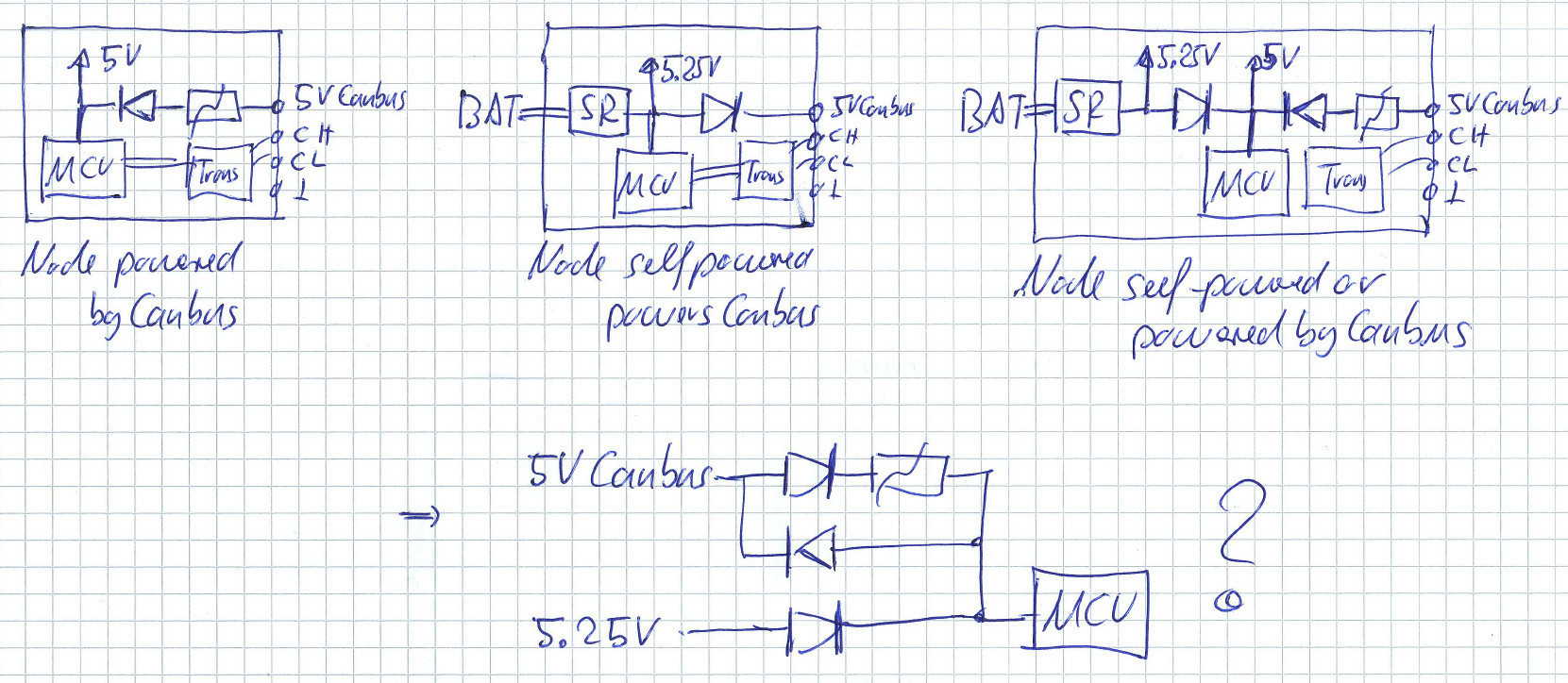
On my bench it seems to work quite well, but as said, I’m not an expert, far from it, and would miss all the trouble points and .
Cheers, Olli