Let me preface by stating how impressed I am by this open source community, it’s amazing.
I have bought a cube/Herelink combo where I aim to drive a boat with two 24V motors. I have not connected the motors yet, and am using an oscilloscope for measurement. I have traversed the setups and forums, but I seem to lack some fundamental connections in my mind to truly understand what’s happening on the servo rail and its setup.
My questions are as follows:
What are the connection between the RC channels and the channel modes? As far as I understand, each channel (RC1, RC2, …) can be linked to a signal pin on MAIN OUT. Each of these signal pins then deliver a PWM pulse. What are then these modes, what does it mean that they have different PWM numbers behind them (MODE1 - PWM 930-1230 etc)? Do different modes occur as I increase my PWM signal with the joystick?
Why am I locked to 5-10% duty cycle, and is it a way to surpass this? Since I’ll use boat motors I thought it best to use 0-100% PWM, but cannot for the life of me figure out how.
Following is my parameters, please tell me if something looks wrong:
MODE_CH: 8
MODE1-6: 0 (Manual) (What do these do anyway?)
RC1_OPTION: 51 (Manual)
RC3_OPTION: 51 (Manual)
SERVO1_FUNCTION: 26 (GroundSteering)
SERVO3_FUNCTION: 70 (Throttle) (Does not work, however RCIN3 works but is not recommended in wiki? Also restricted to low duty cycle.)
Also, setting SERVOX_MIN/MAX and RCX_MIN/MAX from 0 to 16000 or 20000 does not give me the full duty cycle as wanted.
The MODE_CH and MODE1-6 allow you to use a channel on your remote control to change the mode of the flight controller. You can assign a mode to each of 6 “zones” of the channel position. So, for instance, suppose channel 6 is a pot that can pan from left to right on your remote control and you want to use it to control the mode of your flight controller. As you pan channel 6, the Ardupilot will see a value roughly from 1000-2000. This range is divided into 6 roughly equal zones. You can assign a mode to each of the zones. For me, I only assign 3 modes to the channel, so I duplicate 2 adjacent channels. I have these settings:
Note that PILOT_STEER_TYPE will determine how your remote control operates. I have it set to 0 which puts my throttle on channel 3 (the left up/down channel) and the steering on channel 1 (the right left/right channel). If you prefer to drive your vehicle (boat) like a tank, set PILOT_STEER_TYPE to 1.
As far as the range of your PWM values, you set them on the Initial Setup tab under Servo Output .
I hope this helps you get started. I was totally confused at first myself (and still am sometimes!). As you said, the folks on this forum are super. You will get the help you need!
Thanks a lot, ktrussel! I now have working skid-steering! I do however have a couple of follow-up questions if you do not mind:
Throttle response is quite slow, taking approx. 2 seconds to obtain full throttle. How could I configure this, to make it faster?
Only upwards throttle is possible, and I wish to achieve reverse propulsion as well. Any ideas on how to obtain this?
I still wish to increase the PWM duty cycle range beyond ~1-2 ms to its full potential of 0-20 ms, and changing it on Initial Setup - Servo Output only allows me to stay within maximum range of 800 - 2200 microsec. Any other way to surpass/change this?
David_Boulanger: RCx_OPTION certainly was a problem, setting it to 0 fixed it! However, my current full parameter list is attached.
I believe your slow throttle response could be from your MOT_SLEWRATE parameter setting of 30% per second. See documentation at http://ardupilot.org/rover/docs/parameters.html. Mine is set at 100%.
I can’t help you with ESC issues. I have not worked with them. My rover is a gasoline powered mower.
I am no expert on RC PWM signals, but I do not fully follow your reasoning on “PWM duty cycle”. The general way these signals work (I believe) is that there is a pulse generated about every 20 ms (a 50 Hz frame rate). That is constant. The pulsewidth of the pulse will vary from 1 ms to 2 ms. So, the flight controller hardware/software ranges of 0.8 to 2.2 ms is made to accommodate that standard pulsewidth range with 0.2 ms on each end for tolerance variations. I’m not sure if this helps or if I am way off on your question/concern.
David_Boulanger: Throttle response in manual mode. Hardware is what I stated in the beginning, I’m using a Pixhawk 2.1 (Cube) and a Herelink RC system. I have plugged an oscilloscope directly on the servo rail of the Pixhawk, and the response from this is what I am interested in at this moment. The motors work such that 50% duty cycle equals no power, 100% duty cycle is max forward and 0% duty cycle is max backwards.
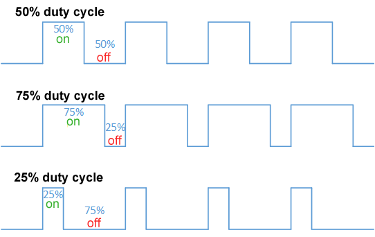
ktrussell: My MOT_SLEWRATE was also 100% actually, but disabling it by setting it to 0 solved the problem, thanks! It is now as fast as I had wished for. With regards to PWM, duty cycle is the amount of time the output pin is set to high relative to the “full cycle” which is 20 ms when framerate is set to 50 Hz. Alas a 1 ms pulse equals a 5% duty cycle for a 20 ms cycle, 2 ms pulse = 10% duty cycle etc. Visual example seen by https://upload.wikimedia.org/wikipedia/commons/b/b8/Duty_Cycle_Examples.png
I also am not quite sure how the pulse width is translated in ardupilot, but normally an e.g. 8-bit signal (probably baked into a mavlink message in this case) is sent every 20 ms over radio, where a value between 0 - 255 translates into a percentage of the duty cycle, and the microcontroller in question sets the output pin to high for that amount of time. Many applications allows for usage up to full duty cycle (a full pulse width of 20 ms in this case), but I struggle to find a way to do this on the Cube.
However, if I am mistaken, please do correct me.
EDIT: I certainly was mistaken - at least in part. I did not now there was a difference between RC PWM and PWM for DC motor control. I need to find an appropriate ESC to translate the RC PWM into the motor controls PWM for the motor I bought. It seems so obvious now… but I did not understand the difference between the two. If anyone else have been confused in the same manner as me, these articles made me understand:
Thank you very much for your input ktrussel and david_boulanger - I have everything set up as I wish (for now lol). This thread can now be considered resolved on my part
I have only tested it indoors as of yet, as I’m still lacking some parts, but so far I am quite impressed. Clear and quick video from camera, sturdy joysticks and clean design. I believe it was painless360 on Youtube that gave it a range test, and got clear video feed from 16 kilometers (!)
@OriginalUsername5, I started to ask if you were somehow talking about the motor PWM, where going from 0 to 100% duty cycle is what you need to go from 0 speed to 100% speed. Glad we are on the same page now. The parameter file you had uploaded had the slew rate at 30% but at any rate, glad that is resolved. Keep us posted on your progress.
