I would need to understand why you had the roll over but generally I wouldn’t say that you would lower this parameter to protect against roll over. Now I think I see why you had large VFF values. Due to the ATC_ACCEL_MAX being so low, you tried to compenstate with large VFF. The ATC_ACCEL_MAX and ATC_INPUT_TC should be set so as to fit the aircraft response you like to see. You can even use the ATC_RATE_MAX parameters as well to provide the feel you like. So these parameters provide the desired response that you see in the log. The PID and VFF parameters are used to make the aircraft actual response match the desired.
So the notch should not be made too wide. only use it to cover one harmonic. You might get some unexpected oscillations. I chose the 2/rev because it was showing through even with the low pass filter down to 6hz. I would leave the notch at the 2/rev and lower the low pass filter down to 6 hz again since the 1/rev is showing through in the response. it isn’t terrible but you can see it in the roll axis.
I don’t know but I do know that it affects the I term and causes problems with the tune of the helicopter. So please keep it disabled.
Not particularly. We can look at yaw as well. why did you lower ATC_ANG_Y_P to 2? I guess I would recommend putting it back to 4.5 and lower your ATC_RAT_YAW_P to 0.2. then raise ATC_RAT_YAW_P until you see oscillations and then cut the gain in half. We can look at the response after that.
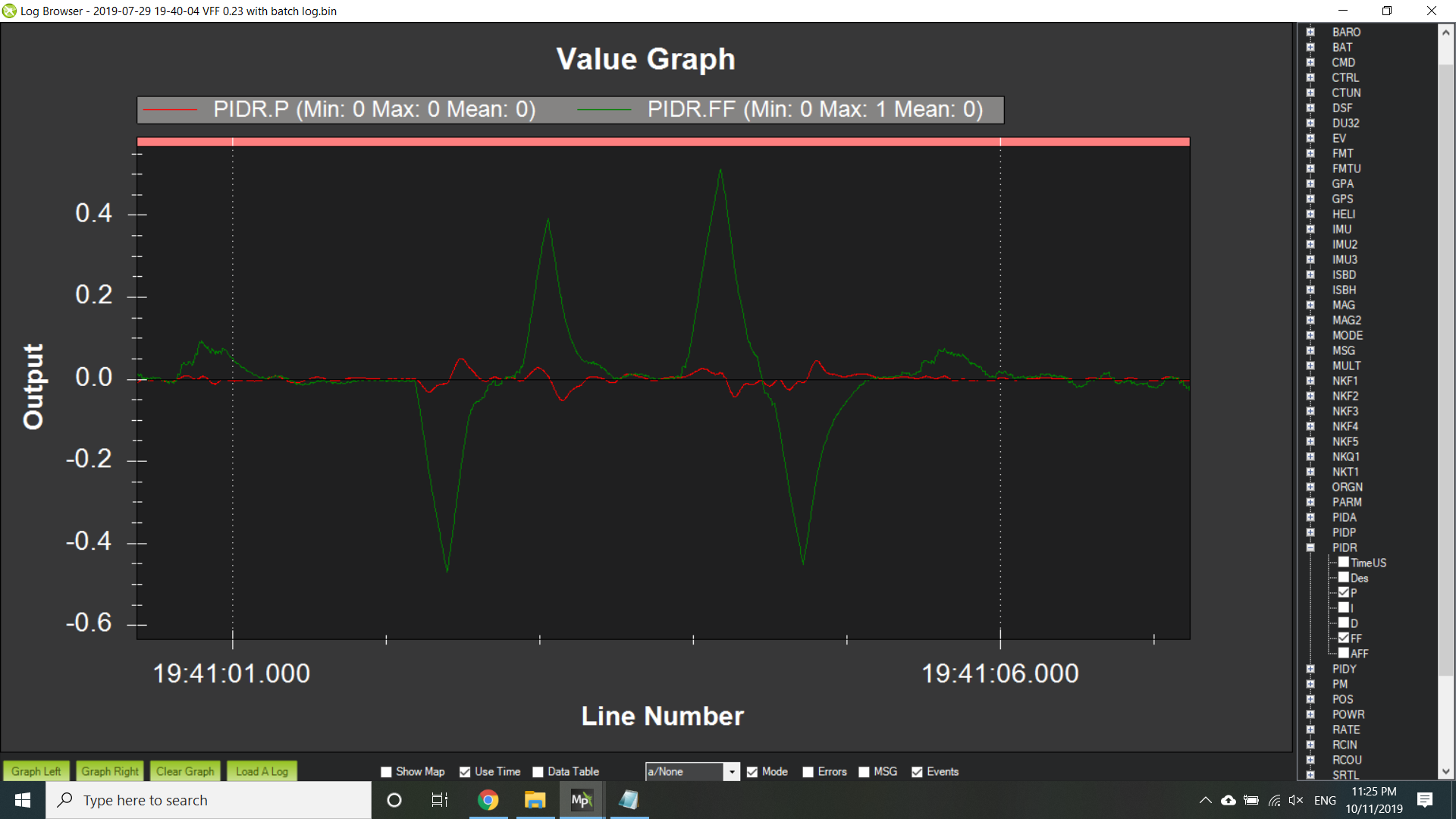
Now about your current data you provided. I want you to increase your VFF for both pitch and roll axes. You want to look at your PIDP and PIDR messages and for each axis look at the FF and P signals. PIDP is the pitch axis and PIDR is the roll axis. During the input you want to see the P signal go initially in the direction of the FF signal but then reverse and go in the opposite direction just as the FF peaks. As shown below.