Bill, thanks for posting this!
I initially did a lot of bench testing, logging the ThO vs SERVO8 output, trying various curves, and graphing them in APM Planner2. Once I was satisfied it works on the bench I did a ground runup without blades to test it for runaway, or improper throttle response. It passed the ground runup test easily. I made a vid of that run
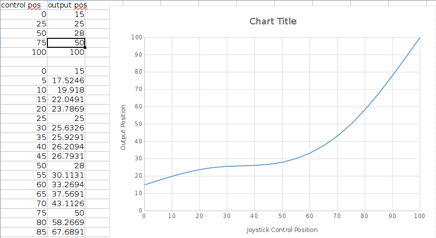
The weather improved in the mean time and I flew it. I first disabled the governor and flew it just on the throttle curve to fine tune the points and get smooth response with no governor. I ended up with a 25-30-35-50-100 throttle curve for the 766G. Then I enabled the governor with a 30% “stick switch”. What the “stick switch” does in a piston or turbine governor is enable the governor at a pre-set point on the throttle curve. With combustion engines this allows starting the engine and idling at ground idle-rotors not turning for warmup. Disengaging the throttle hold (enabling “motor interlock” in ArduPilot parlance) spools up to ground idle-rotors turning with the collective at bottom. As the collective is advanced, when the 30% throttle point on the curve is reached the governor takes over and takes 10 seconds to reach governed headspeed.
The points on the throttle curve with this new system do not correspond to any collective pitch angles as the old system did. It is like the typical RC radio and the five points correspond to percentage of collective range. So with a typical UAV setup running, say -3 to 11 degrees pitch, we have 14 degrees of collective range. So, as an example, the H_RSC_THRCRV_50 setting corresponds to 50% of the range, which is 7 degrees, or 4 degrees of positive pitch. This will be instantly understood by anybody that has ever set up a throttle/pitch curve for a RC heli - it is standard procedure. The old system was somewhat confusing, for all but 3D setups using a V-curve.
Hover collective pitch ranges from usually 5 degrees to 7.5 degrees of positive pitch for most helicopters. So we’re “on the curve” between the H_RSC_THRCRV_50 and 75 points in hover with the example noted above. This smoothly increases power, or throttle opening, as the main loads to takeoff pitch without the governor having to do anything if the curve is set properly.
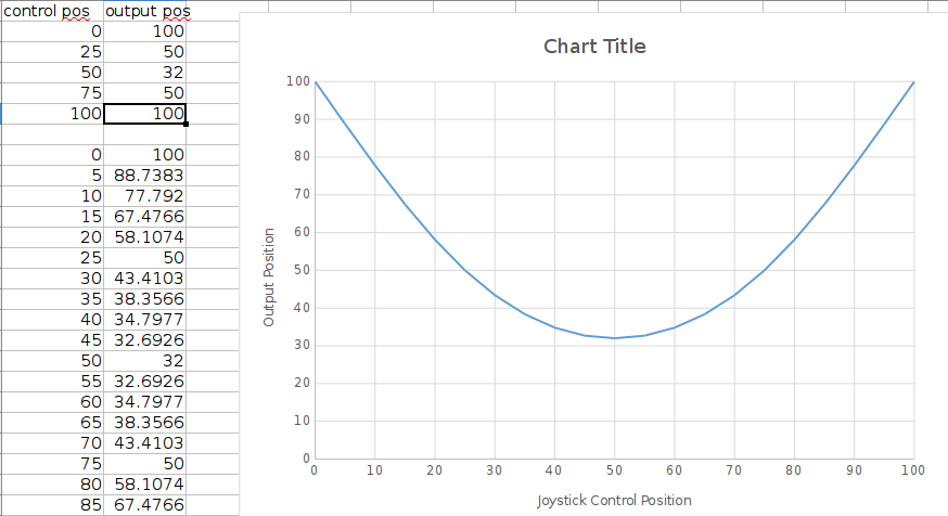
The response of combustion engines to throttle opening is not linear. It is more the shape of the curve that Bill posted above. There is quite fast response to small throttle opening changes at <50% throttle opening. From 50% throttle opening to WOT, there is much less change in power output vs throttle.
All modern governors, as explained in the video, “read” the throttle curve for feedforward to provide faster response to load changes. That curve has to fit the torque curve of the engine or you get either over-speed or “lugging” on quick collective lead-in.
After making a few tweaks to the governor settings to fit the tuned throttle curve it was as close to scale quality throttle handling as it gets in helicopters. I was able to achieve picture perfect transition from the governor back to the throttle curve after landing, when reducing power to ground idle-rotors turning, before disengaging the clutch. Huge improvement over the old three-point linear “curve”.
The final thing this does is provide fallback to the throttle curve if the governor sensor fails in flight, which absolutely requires a properly tuned throttle curve for a piston or turbine engine.
H_RSC_MODE 2 is redudant and not needed. Simply set a flat throttle curve like is done in RC radios for electrics with governor. MODE 2 is also redudant with the current 3-point curve, so I’m not totally certain why MODE 2 even exists. If you want 75% for an electric governor, just set all the throttle curve points to 750 and it works identical to MODE 2.
This will fly an electric with no governor. It is done with RC radios all the time. It’s just a mattter of fine tuning the curve to fit the motor’s torque. Electrics are considerably different from combustion engines. Testing on an electric platform is underway. Should have feedback on that soon.