Yep. There is. You have to talk to Jerome at Drotek and order one. Ready Made RC is the US dealer and you’ll get a plastic one from them. They don’t think that anybody thinks it’s worth the extra $55 bucks for the aluminum case. But it is.
It’s interesting with the PH2-style controllers. In a two-stroke piston machine, with the engine idling at 5,000 rpm, if you touch the top of the “Cube” module it feels like touching a buzzer. You can touch any other part of the frame, the engine itself, servos, whatever, and you don’t get that feeling. The CUAV V5 and PH2.1 are the same. The flat-case controllers with aluminum case do not exhibit that phenomenon.
The Control Zero comes with a servo rail adapter breakout. It comes with a lot of cable accessories that make it pretty easy to build your connectors as you need.
I liked your experience! When I was a student, my teacher said that all the great discoveries in science were made on primitive equipment. You wrote in English with a Russian style of your thoughts, so I understood this on Russian. Thank you for your useful work on the rational use of air FC I’m going to use a flight controller Holybro Pixhawk 4 on a large model with an internal combustion engine. My flight controller will be adjusted with the addition of ballast until the vibration is reached the optimum value
As I understand it, for a rotor speed of 1800 rpm (30 Hz) we need to look at the values for 30Hz, 60Hz and 120Hz).
Can this same approach be applied to fixed wing/VTOL aircraft primarily operating repititive and predictable autonomous missions? What I anticipate is:
Propeller RPM would be varying. However, for predictable and repititive AUTO missions, we could:
a) Optimize for the average range of cruise RPM in case of fixed wing or fixed wing flight modes (in case of VTOL)
b) For the climb and descent during VTOL flight sections, use a similar approach but precedence be given to fixed wing modes since that’s where the aircraft will spend most of its time.
In this case we’d need to look at the values of 90Hz to 180Hz (and maybe some harmonics of the cruise RPMs)?
@ChrisOlson RMRC had a couple of aluminum cased Pro 3s in stock so I ordered one, will post results once I can. Very impressed with the form factor/layout, I do wonder how the non-temperature controlled IMUs will go in the cold up in Canada. In saying that I haven’t been particularly impressed with the Cube Black’s heating, it seems that to me that IMU1 is heated way quicker than IMU2 which causes a few inconsistent gyro/accel messages when I’m itching to get flying.
@egunak95 thanks for the kind words, with your approach I think you should be able to find good results.
@Arunabha42 with a fixed wing I doubt that you’ll have a consistent rpm with a fixed wing platform due to wind etc. In all new builds I would recommend firstly reducing mechanical vibration as much as possible before then choosing a good flight controller for the application, isolating the flight controller well if necessary and then targeting the specific vibration frequencies using all the tools available; the harmonic notch filter (https://discuss.ardupilot.org/t/tuning-the-harmonic-notch) to target mechanical frequencies (prop rpm etc), the static notch filter to target control system instability frequencies and the low pass filter to filter all other noise.
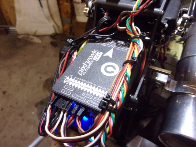
I was working on this helicopter that has a PH3 Pro on it. The control is mounted to the tray with a 2" wide strip of velcro under it, directly above the engine’s cylinder. Vibration is perfectly acceptable, it never clips the IMU’s, the helicopter handles with FBL-unit precision.
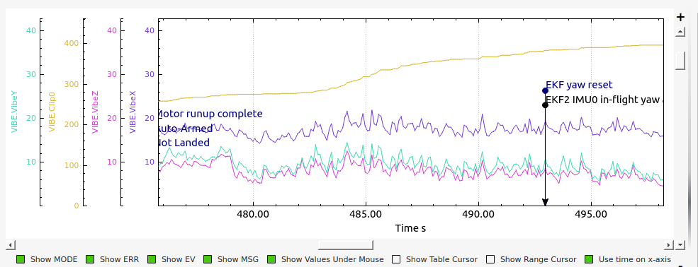
So this is not a scientifically done experiment, or using any standardized test method. Just an observation. Since I had the cowling off it and the controller is exposed I stuck two 1oz flat lead wheel weights to the top of it and test flew it. It did not handle properly at all.
I pulled the log and looked at it and with the weights on it it had excessively high vibration in the X-axis. And it had a steady clipping of both IMU’s. Same phenomenon as the “Cube”-style controller - touch those weights with the engine idling at 4,450 rpm and it feels like getting a shock in the tip of your finger from the high-frequency vibration.
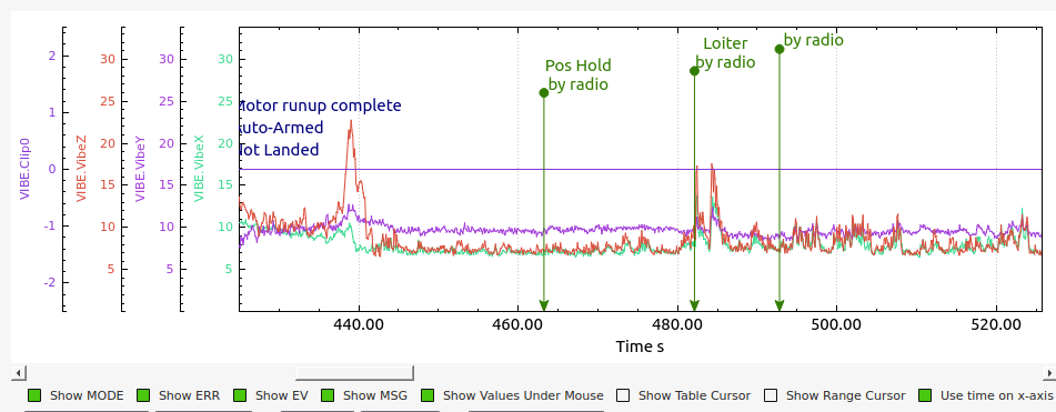
I’ve seen the recommendation given to stick tire weights to it to add mass to the control and reduce the vibes and clipping. I’d like to point out it doesn’t necessarily work that way. It CAN if it damps certain frequencies that are causing a problem. But it can make it worse too.
The engine in this helicopter runs at 11,450 rpm at governed speed. 380Hz vibration from the acceleration of the piston and resultant acceleration of the crankcase as the piston reverses direction twice per revolution. The power stroke is more prominent than the compression stroke so it amounts to a fundamental of 190 with a second harmonic at 380. It’s that second harmonic that kills the IMU’s in my experience. Anything mounted above the control that can couple with that at its natural frequency will amplify it. Since the primary accelerations from the crankcase are fore and aft (cylinder faces ahead), the x-axis is what kills it with those weights on there and causes the IMU’s to clip. The controller by itself without any added mass (in the wrong place) does a perfect job of damping that with the internal damping mechanism in the controller - as long as it is mounted with a relatively solid mount. If I put any sort of soft mount under it, foamy blocks or whatever, it is back to the same problem as putting the weights on it - it will clip the IMU’s.
Yes we are using them on both our 13" quad and our 10" quad. Dare I say it’s my favorite flight controller to date? Super small but very powerful. mRo also has excellent customer service. Beats the heck out of Cube support
Chris, thanks so much for the real world testing. As you say, the vibration levels look good and the internal isolation must be handling those frequencies perfectly. I haven’t had any experience with gas helis; can I ask if you’ve done an FFT on that particular heli? Are the vibes due to the engine much greater than the vibes at rotor frequency and 2*rotor frequency (I’m guessing they are?)
Looking forward to recieving the 3 Pro to do some testing.
No, have not done any FFT on any heli’s. And yes, the engine is the primary source of vibration, both from mechanical vibration and noise. The rotor vibration frequencies are not detectable. Bill had me try some experimental software some time back that was supposed to detect the rotor rpm using the vibration. It did not work.
However, the rotors have been balanced and tracked on my helicopters using a RPX DynaTrack with the strobe. So it’s not going to be able to detect anything at that frequency because it doesn’t exist.
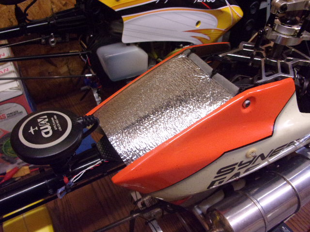
I had to snap this photo to show something interesting. This is a piston 800-class machine with a V3x in it
That silver material over the flight control - what is it? It is a foil-backed thin foam insulation material that comes from those accordion things that you can fold out to put in the windshield of your car to keep the sun out. My wife wondered what happened to hers. I told her I noticed it was old and I need it and she needs a new one. She said it she just got it two weeks ago. Ooops.
But that stuff is handy. With that stuff over the control vs not being there it reduces the vibration by about 25%. Vibes in all three axes run 4-6 on this heli.
Since it is impossible for it to do anything for mechanical vibration I attribute the reduction in vibration to a reduction in noise with that thing over the controller. You can see where the outlet of the muffler is and that’s probably about 120-130 dB right at the exhaust tip.
Interesting that you weren’t even able to pick up rotor frequencies, I would’ve thought maybe even with great balance and tracking you’d be able to find traces of say rotor wash impacts on the fuselage/tail boom.
Also, great ingenuity with the foam insulation, very impressive you’re able to get such low vibes on a gas heli.
When Bill had me try that custom firmware build it would pick it up during runup, but then it lost it. The rotor was balanced and tracked at 1,530 rpm.
Those survey helicopters have had considerable work done to the engines for doing camera work. It’s not in the flight control or mount. They are 2mm stroker engines. Just like the rotor, they have some vibration during runup. But once they reach the speed they were designed to run at they are as smooth as a turbine.
My guess is that it shields the unit from the mass of fast moving air coming from the rotor. That air could induce vibrations, expecially if it hits cables and make them vibrate, the pretty long you have in the back of the unit i mean.
Just a guess.
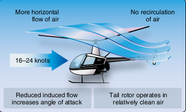
It is certainly possible. However, the downwash velocity is not all that high at that location in hover. In forward flight it could be. The inflow to the main rotor in forward flight is from the front, then downwards and back underneath the rotor. It flows directly over the tail rotor, which increases the tail rotor efficiency in forward flight.
This occurs at the translational lift speed of 16-24 KIAS in all helicopters when the nose comes up all by itself and they start to fly like a fixed-wing instead of using brute power to move air mass equal to the weight of the machine. It is called “blowback” by helicopter pilots but the aerodynamic reason for it is much more complex.
I have noted the reduction in the measured vibration with that cover on there at all air speeds and flight profiles.