Hello everyone, I’m planning to implement some autonomous features from ardurover to my tractors and for this work I must know if the firmware has a important function known as Terrain Compensation.
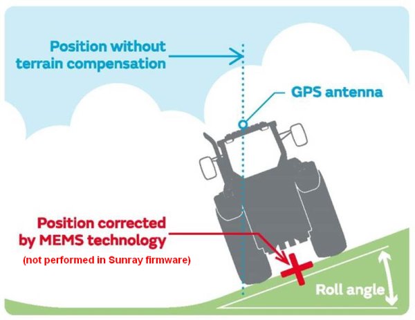
What it does, looking at the image below, you can see if I mount my GPS on top of the tractor (about 2.5m height), when the roll angle changes, the real GPS position changes a lot becouse the GPS mount location, so it needs some fix to compensate this changes and with this i’m able to maintain high accuracy from RTK.
There are parameters to set the offset of your GPS from your CoG / IMU / autopilot. Maybe if you set those to make it look like the autopilot was on the ground (i.e. between the bottoms of your wheels) you would get the result you’re looking for.
Hello everyone,
Sorry for adding to this old post. I just wanted to confirm if ArduRover does indeed do a full lever arm offset calculation using the orientation / attitude information derived from the IMU’s? In other words, if the goal is for a rover to follow a predetermined path with the center line of the rover following that path, it’s important that the GPS position at the antenna be recalculated to represent the center line of the rover / tractor if the GPS antenna deviates from the center because of terrain variation. I know the GPS antenna offsets relative to the flight controller are existing parameters, but just wanted to confirm that once these offsets are entered as parameters, the GPS position is no longer necessarily the position of the antenna but instead the center of the rover.
Thank you!
I dont know of any vertical offsets that are able to be adjusted to achieve what you are referring to. I guess if it was in the code it would definitely be mentioned in the rover docs, and one could always test this very easily by putting a large height offset in (if such a value exists in ardupilot) and then tilt the flight controller and see if the reported position moves with the tilting. I know this is all allowed for in trimble etc but as far as i know it hasn’t been done in ardupilot
Thanks for the reply. This is generally referred to as a lever arm correction (in this case, the lever arm is the offset between the GPS antenna and IMU) and as you mention almost all commercial INS have this correction capacity built in. However I didn’t see this lever arm terminology used in the ardupilot documentation (although I did not look too hard) which make me wonder if the correction is fully implemented.
However as you mention it should be easy to test, especially if RTK GPS is being used.
After a long time, i’m back with this project. After reading all new posts, I found out this senso compensation Sensor Offset Compensation, maybe it is the feature we’ve looking for, i’m not sure it does the correction mentioned in my first question, I dont know when, but I’ll test it and i’ll bring the results for you.
If someone already tested, please, post your results.