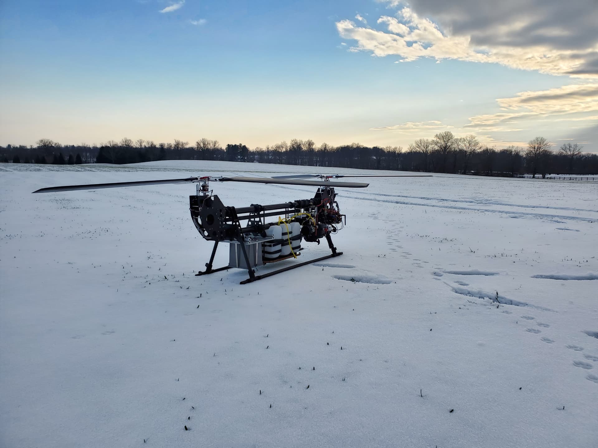
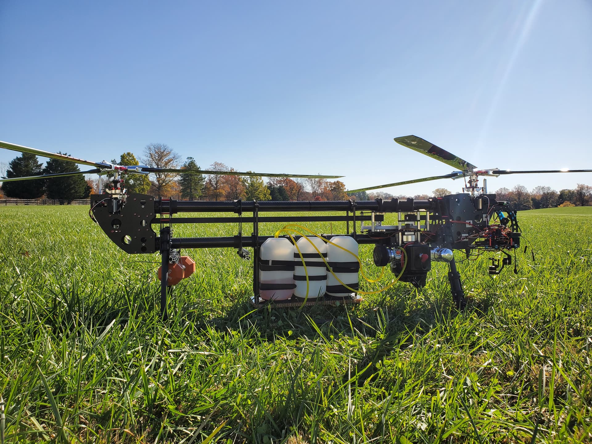
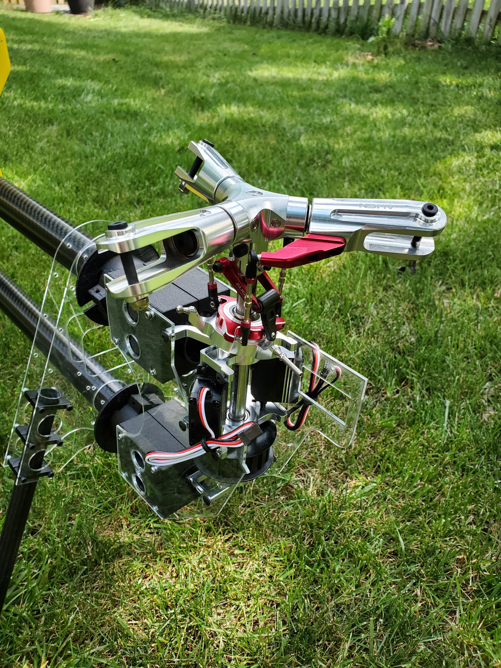
I have been working on a tandem heli design off and on for a few years now. I see very little on the forums about tandem helicopter designs and I think they have some amazing benefits so I wanted to show my journey and create a place to discuss the design. The version in the picture is designed to fly about 3 hours while carrying a 12lb of payload. It weighs roughly 53lb with full fuel and payload. Aircraft weight is about 29lb plus about 12lb of fuel and 12lb of payload. It has a single gas engine in the center which runs power to the ends using belts. The heads are off of an Align Trex 700 and most of the rest of it was designed from scratch using onShape CAD. It runs a cube orange autopilot and a herelink system. Although I found the herelink transmitter tough to use in development so I mostly used that for telemetry and video transmission and relied on a simpler TX for testing.
It does fly, but I never got it tuned up well. It had a lot of issues with belts slipping and I had to redesign the belt system a number of times. At the end of the day it has a number of technical issues and some are hardware based and others are software. This blog is meant to be a start to documenting how it all got started, how I fix everything and the journey to learning the tandem heli firmware better so I can tune this up correctly.
Hello, I reverted to BLOG as there are really interesting pics and data.
Good luck for the next steps and hopefully the experts of the ArduPilot community will help
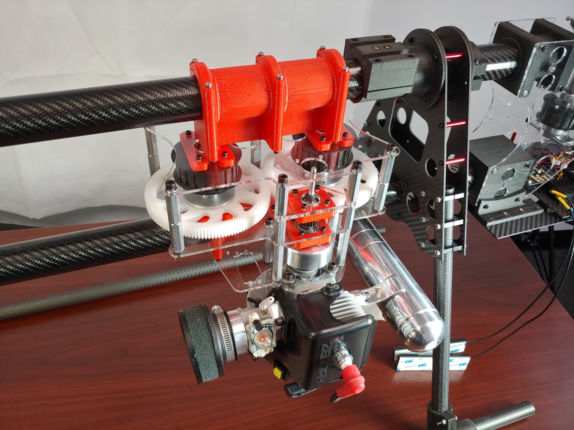
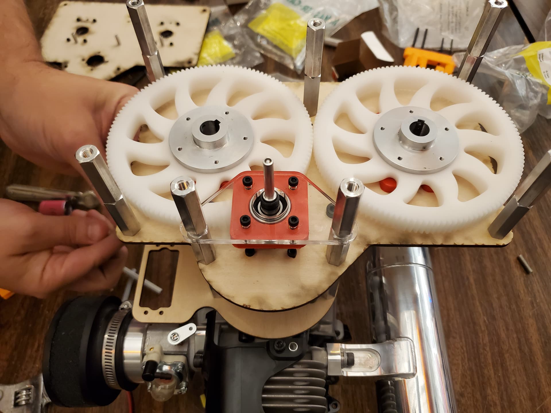
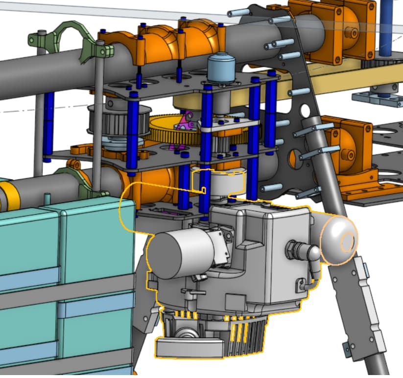
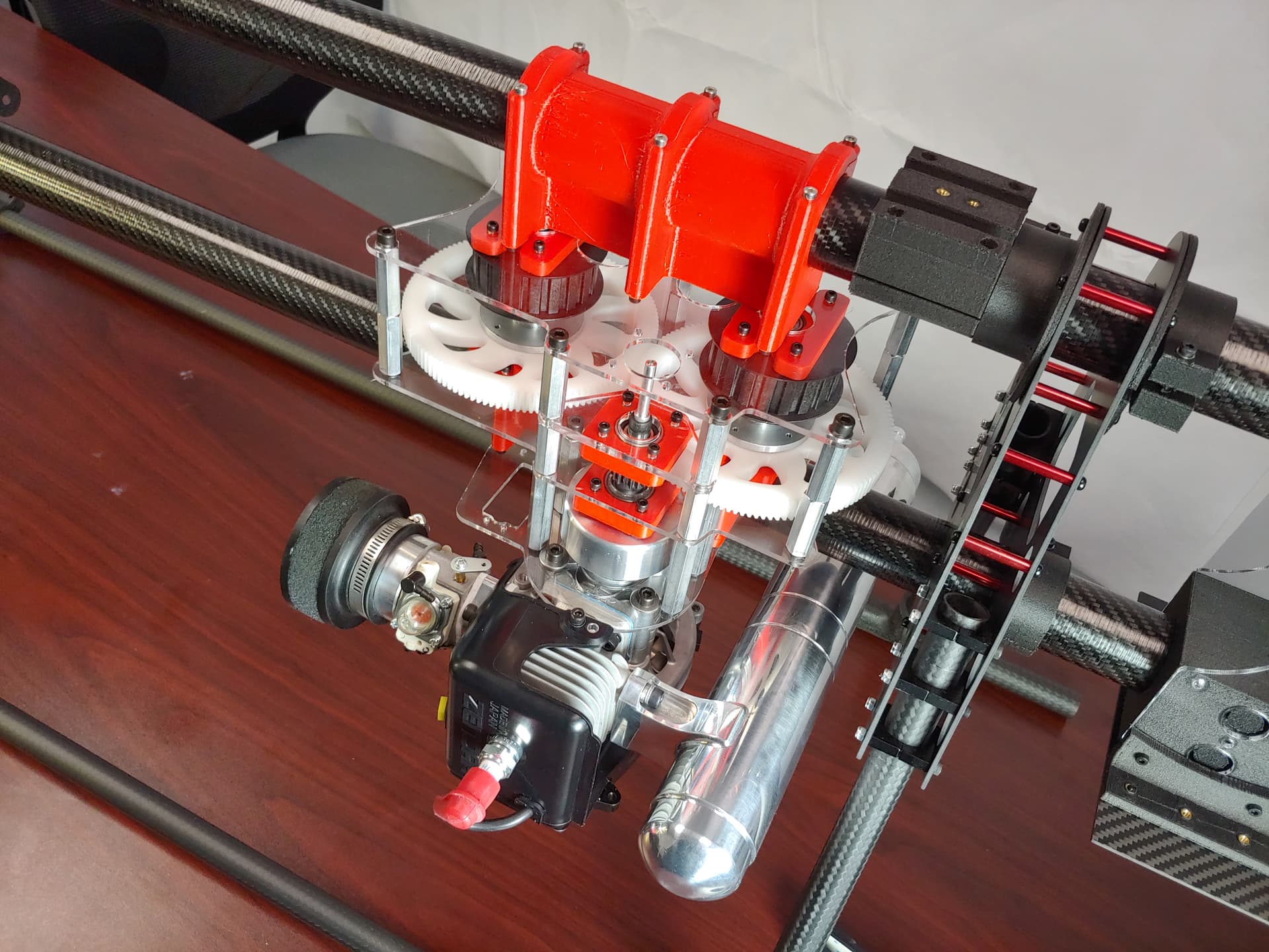
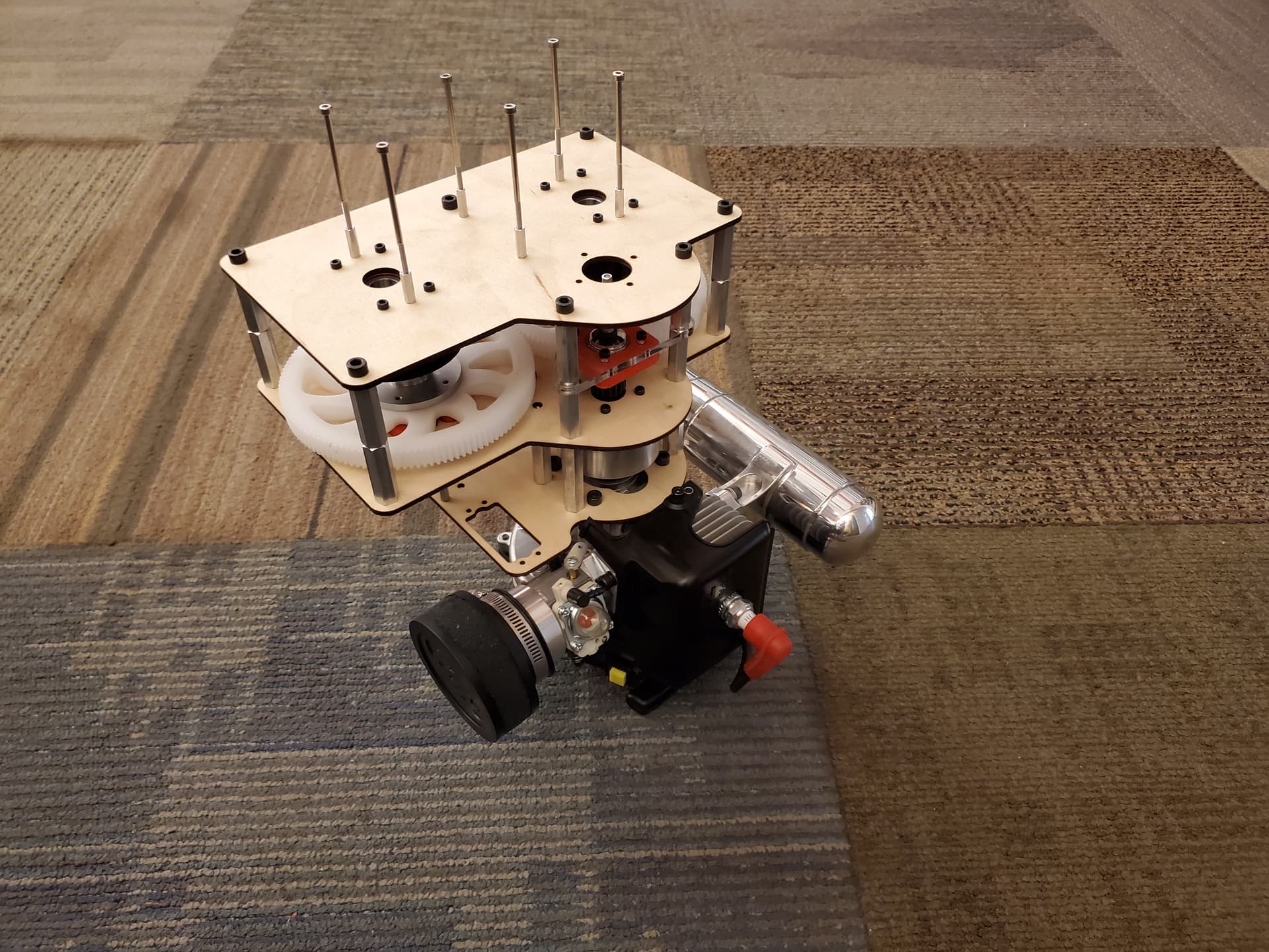
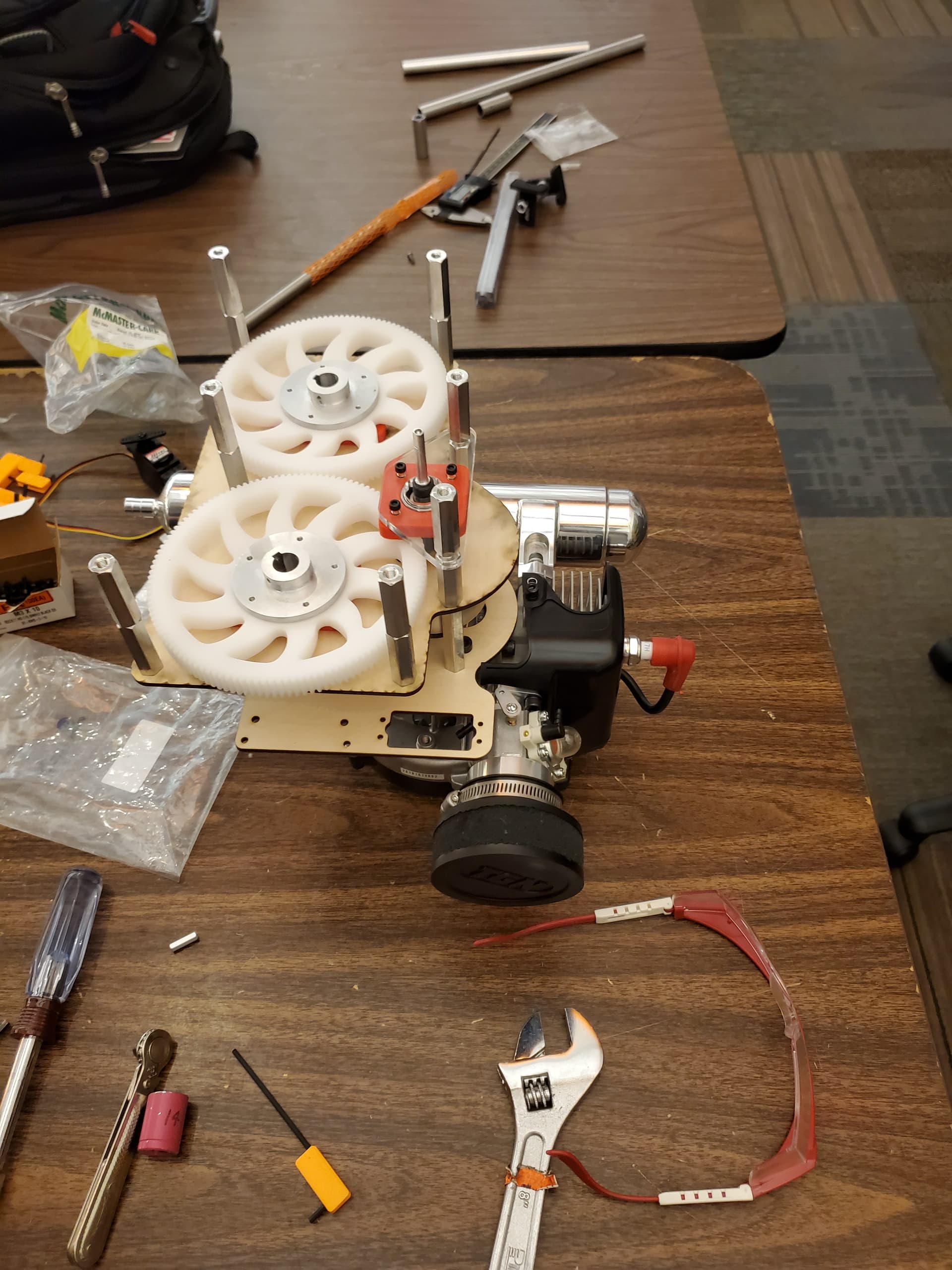
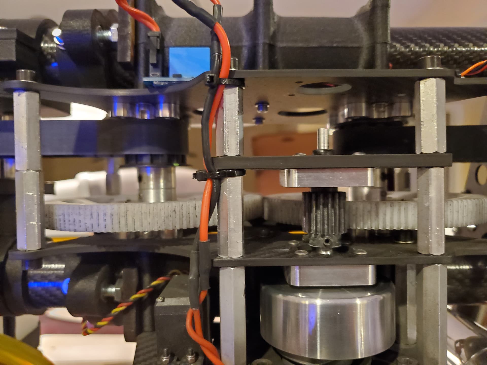
I thought I would share a little more detail on the engine setup since this drove a lot of the design. The engine likes to run at about 11k RPM so it needed a serious gear reduction and transmit the power to the main shafts. The RPM reduction needed to happen right at the engine because belts or a drive shaft would not be happy at that RPM. I ended up using two miniature aircraft main gears to do most of the reduction. This also gave me the opposite rotation needed on each main shaft. I got everything mocked up with PLA 3D printed parts and laser cut acrylic or wood. Neither of these materials are strong enough to for flight, but they are quick and cheap for fit checks before I spend the time to get carbon fiber plates cut and CNC aluminum. The belt system has been an issue over time, but this central engine, pinion and gear setup has been completely rock solid. I have never stripped a gear or had any reliability issues from it what so ever.
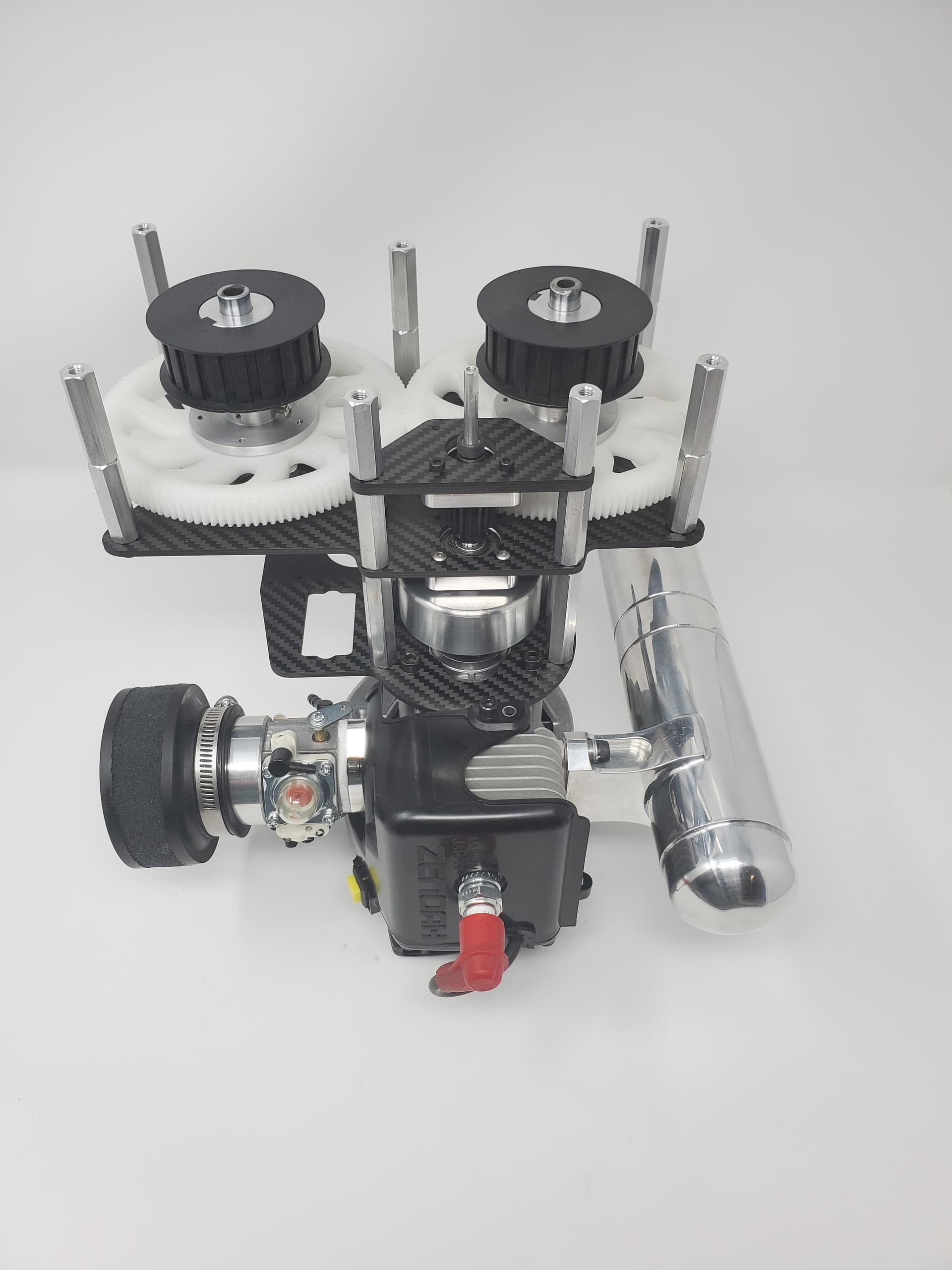
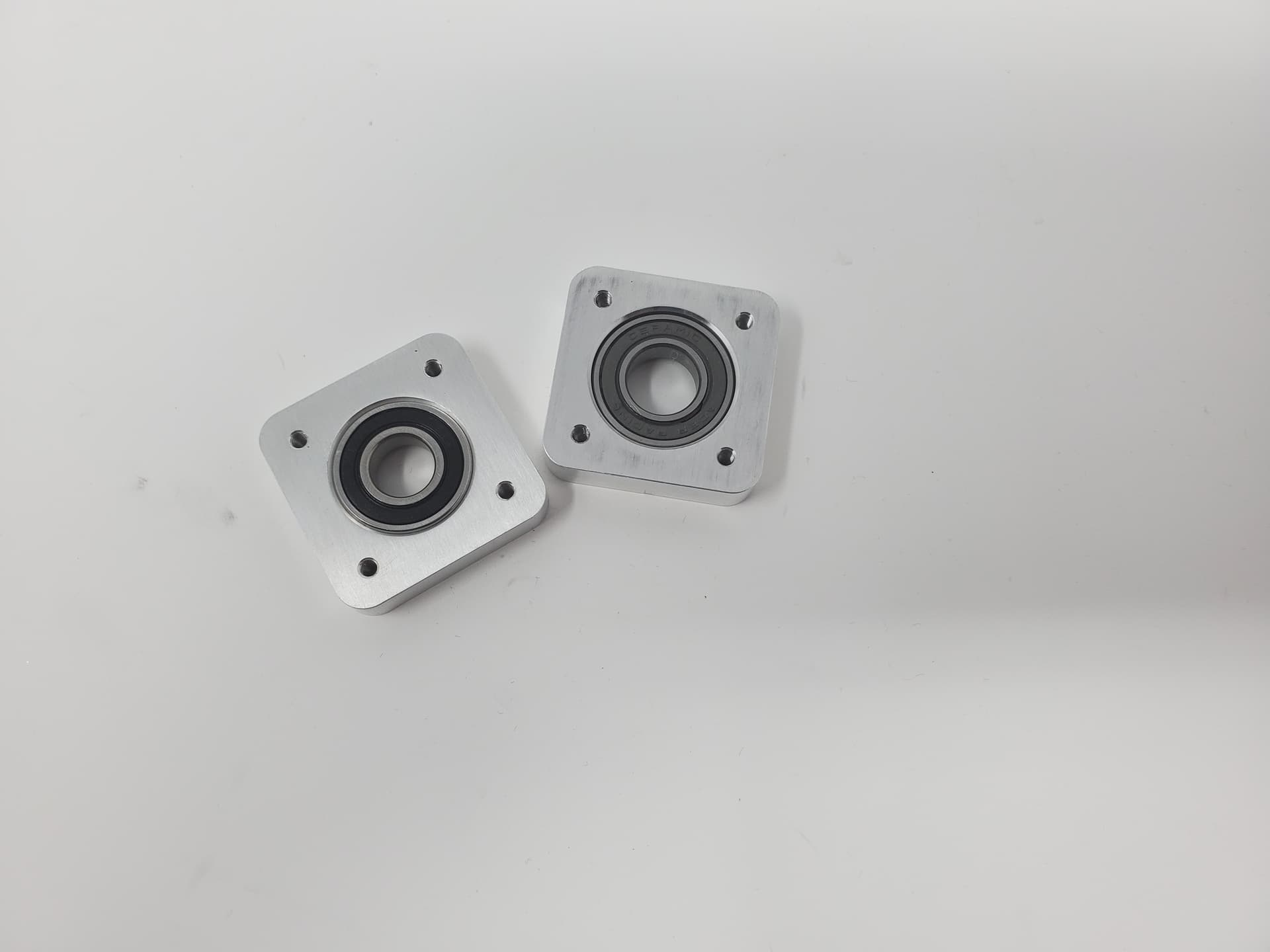
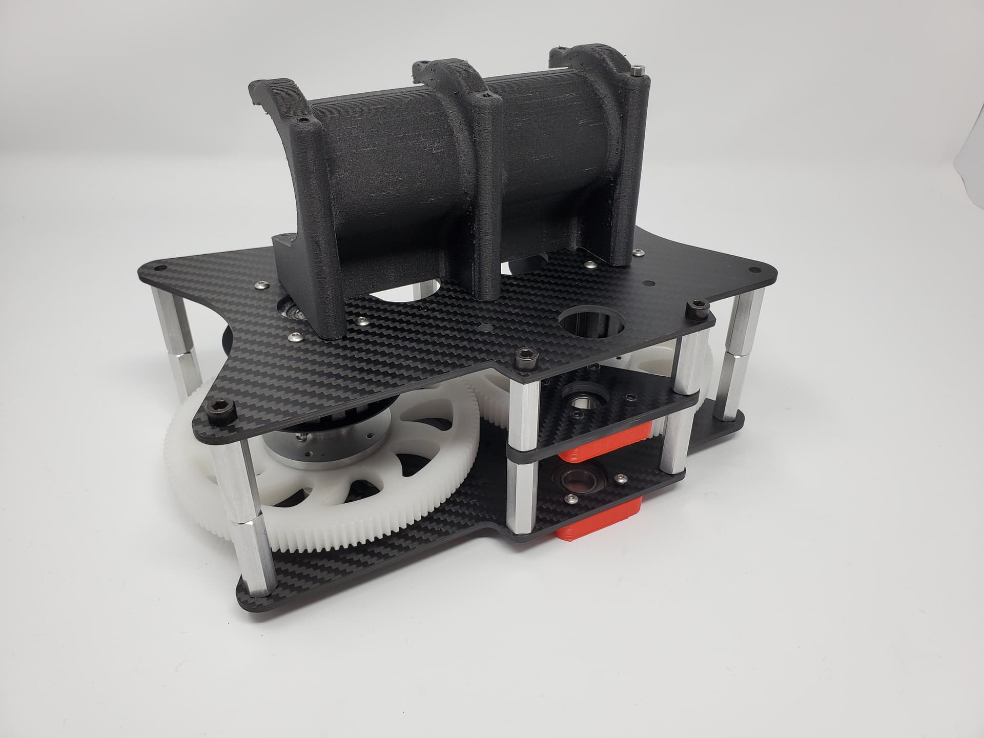
Once it all seemed to fit I then changed over to 3D printed parts that used nylon filament that has carbon fiber in it. I used NylonX filament and this has proved to have just the right amount of strength with just a little flex to deal with the vibrations. I used this for a number of structural pieces and it has worked fantastic! Anything that had a bearing in it or coupled to the power system was CNC out of aluminum and the flat plate was cut from carbon. The 3D printed parts also were printed oversized and I put a rubber isolation in there and then the whole thing clamps on the carbon tubes. Its proved to be super strong and reliable.
For the engine I started with a 28CC engine and that got it flying, but it didn’t have enough power at full weight. Eventually I upgraded to a modified 34cc 2 stroke gas engine which has a lot more power, but still isn’t really enough. The main issue is that the way I did the belts they have to be VERY tight. The tension that is required creates a ton of drag. The entire belt system either needs to be re-designed or move to a torque tube design. I am inclined to move to a torque tube setup, but I have not put in the work to find all the right parts yet. And what I have works, sort of…
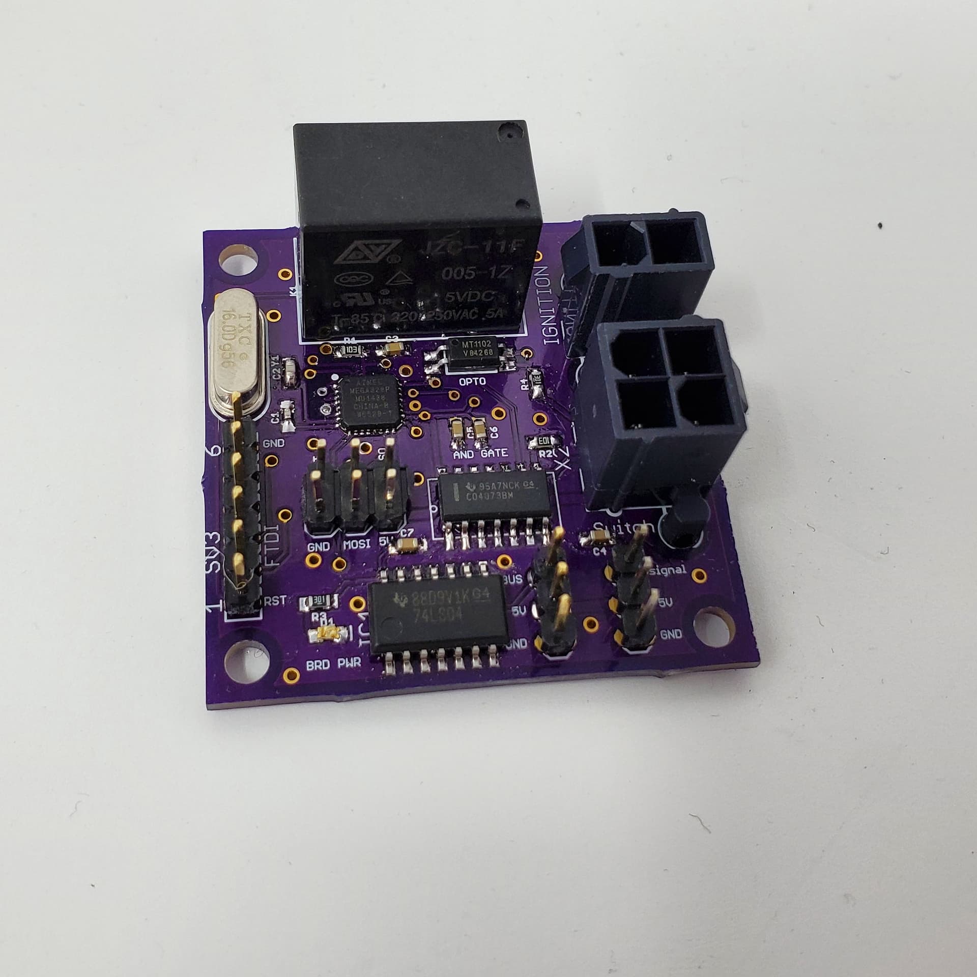
To keep everything safe I wanted to make sure I could kill the engine anytime I wanted quickly and easily. So I designed a PCB which has an ATMEL 328P chip (the same as an UNO) and I loaded an UNO bootloader. The board has a relay connected to the mag and ground it out to kill the engine. I did 3 things with the board, the first is a lighted switch on the copter which has to be depressed to make the ignition live. Then a remote e-stop box which has a heartbeat and that has to be live or the ignition wont come on and the third is a connection to the cube which can signal the engine on or off. If all 3 of these things are true then the live ignition light is on and the engine can be pull started. Considering the size of the copter this was a really important part of the development. The last piece of the engine system is a governor using a hall effect sensor. I was typically running the head speed at around 900-1100 RPM. This is a very low RPM, even for 800mm blades but I am going for efficiency and not sport flying.
Hello @Fred_Briggs,
congratulation for your design and development! I’m an RC helicopter 3D pilot, maybe you know that there are some RC heli design that successfully use belts for motor transmission, but usually it’s a 2 stage transmission, like on Align TB70. As you can see belts are in the first transmission stage, so the belt speed would be higher and the force lower compared to your design, to transmit the same amount of power, because: Power = Force * velocity
You’re also running at lower head rpm compared to the sport helicopter you’re using the gear from, so there should be a huge force transmitted by belts. Which belts are you using? Also the force acting on the belt could be calculated from the ratios and the engine power and compared to the belt datasheet.
Most helicopters big and small run around 200m/s tip speed. It is considered optimal for most applications.
I wouldn’t be surprised if the blades worked best at their design RPM and loading (you don’t want to decrease rotor downdraft velocity too much as critical VRS speed is directly correlated with it).
@beska Thanks, great to meet another heli 3D pilot on here! I have been flying heli’s since the early 90’s and am familiar with the designs you are talking about. To some degree that is why I used belts for this. When designed right my experience has been that belts are reliable, quiet, easy to maintain and cheap. So it seemed like the perfect solution and I am using 3/4" L series toothed belts.
However, ignorance got the better of me and I made a number of blunders in the design. The design you see in the pics is probably version 5 of the belt design and I have done lots of reading on the topic since V1 which failed almost right away. I have also found some calcs to help with the design. Some of my top mistakes were;
I sized the pulleys to small and didnt have enough teeth engaged at one time. The amount of load a belt can take is proportional to the number of teeth engaged and I believe I was using 10 and 12 tooth pulleys at first. This meant I only had about 4 teeth engaged at a time on each pulley which is not enough. I should have had at least 6 and ideally 8+ teeth engaged.
I didn’t put nearly enough tension on the belts. The amount of tension required is a LOT more than I initially thought. Especially with the small pulleys I have been using.
idler pulleys are super important and I had them on the main shaft but even to this day I dont have them on the engine side which is a real problem.
A spring loaded tension is needed for belts this long and I don’t have that which is also a real problem.
Now I am at a stage where I either need to design V6 of the belts which what I have learned or move on to a drive shaft. So I agree that belts can be great and everything that went wrong was bad design not a shortcoming with belts themselves. So the project is at a crossroads and I need to decide if I want to do a new belt design or scrap it and go drive shaft.
@LupusTheCanine Thanks for the note! I 100% agree that my head speed is to low. But also keep in mind that endurance is a key goal here which generally means a lower head speed. To hit 200m/s tip speed I would need around 1800 RPM on the head. Considering my goal of endurance I suspect that optimal is probably somewhere around 1300-1400rpm. I still have a lot of testing left to do to see what works best, but I do agree that the head speed is to low.
My main issue with running a higher head speed is that I couldn’t with do it with what I had. The way I had the belts tensioned to keep from slipping it put a mountain of drag on the system. When you couple that belt drag with 6 giant blades the engine just didn’t have the power to spin up to a higher rpm. So I geared the engine down to a place that the engine could handle and got it flying. But I had to do this at the expense of rpm since it was grossly underpowered. To get more power and get the head speed up I either need a bigger engine and/or eliminate the enormous amounts of drag the belts are creating. I was also doing a lot of testing at full weight of 50+lb. So I am going to trim the payload and get it down to 30lb or so and do the testing at a more reasonable weight which will help.
I really like the engine setup I have now and the engine has been very reliable. So I am not super excited about changing the engine. Also changing the engine means going to a bigger case which means I need an entirely new clutch system which I am not eager to design again. Which leaves me with either changing the belt design to fix the drag issues which is robbing huge amounts of power. Or I could change to a driveshaft which is a lot of redesign work but possibly a better design overall.
How are you mounting the autopilot with the internal combustion engine vibration? I take it that you have vibration isolated the FC, and if you did how did you select the proper gimbal balls/dampeners for the internal combustion engine running… Did you look at logs of the vibes? I am really impressed with your build!
Hi Fred,
Impressive work on your mechanical design. What a great project! Just wanted to introduce myself. I am one of the co-maintainers for the traditional helicopter code. Ferruccio (@ferrosan) is the other tradheli maintainer. I agree that we don’t have many users that fly tandem rotor helicopters. If you have issues setting up or tuning this aircraft, feel free to post in the traditional helicopter section and ping me on your post. If you decide to use the autotune mode for tuning, please contact me and we can work through it together. I designed the autotune mode with a single mainrotor / tailrotor configuration. I have helped one other user tune a tandem with it but we had to use a different method for tuning the pitch axis. So it would be good to see results from your heli. It would help me with changes to the autotune mode to accommodate different type heli’s.
I have one comment on your design. As you may know, yaw control on tandem rotor helicopters is done thru differential lateral cyclic (i.e. for a left turn, the front rotor head is tilted left using left lateral cyclic and the rear rotor is tilted right using right lateral cyclic) which creates horizontal forces at each head to create the yaw moment. Therefore, stiff rotor heads are not the best choice as they don’t allow blade flapping which limits the tip path plane tilt and subsequently the horizontal forces that can be generated. So I am not sure how good your yaw control is but if you are seeing issues with it, the rotor head could be contributing to this.
Thanks! I I did a few things to minimize the combustion engine vibration. The first is that the entire engine and gear transmission system is an independent unit. It then clamps to the two main tubes using clamshell halves. I oversized the clamshell halves and lined them with silicone rubber sheet. So the engine has a little bit of damping isolation from the main chassis. The second thing I did was put all the electronics on a single plate and then put that plate on isolation dampers. So the battery, flight controller, gimbal, etc were all mounted to that isolated plate. for tuning I made enough holes to have something like 12 isolators and then if I wanted to make it lighter I would just take out some of the isolators and use something like 10. It seemed to work well and the logs looked decent so I didnt mess with it much.
I did have a lot of issues tuning it. I have worked on multicopters and fixed wing quite a bit, but the tuning for this had a different scheme that I am not sure I ever complexly figured out. Yaw was OK, but nothing like what you get from a traditional heli. The 3 blade head does have individual shafts and I put the lightest bushings I could find.
Where I am at with the project now is that I want to understand the tuning better and testing on this thing is really hard because its so big. So I am building a small version using 450 heli parts. This will give me a small system to test, tune and try new things which i can then apply to the bigger one. As I get deeper into that I will certainly post in that channel!
Hi Fred, really nice heli! I think the head dampers you find on the market (even the softest ones) might be too rigid for achieving some meaningful flapping. One thing I did in the past to test/ play with different head stiffness was to 3d print dampers using TPU. Using 100% infill and 4degs of conicity gave me the best results, very soft head (for low headspeeds) and they are still flying today!
I have a question that might seem silly, but why not use rotors that are spaced further apart to prevent contact and opt for two engines instead? Differences in rotor speed could be compensated for by the control scheme adjusting the pitch of the blades. This method appears to reduce mechanical complexity. Where am I mistaken? Thanks.