Is it possible to generate the digital signal from any PWM port (main out or aux out) of the cube orange+ to control the switching of Relay module operating at 5V.
what relay module are you trying to use?
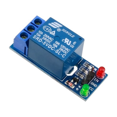
This is the relay module I want to control from the cube orange+.
those modules dont work very well with ardupilot as they want a low signal to activate.
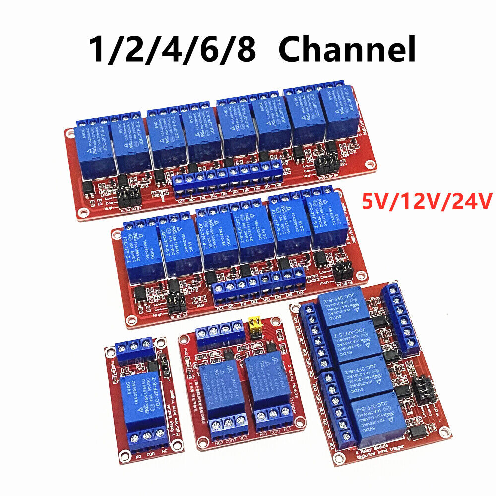
look for the red version as it has jumpers that lets you select activation with a high level signal and will work fine with your cube with the pin set to GPIO relay output.
1 Like
What are the parameters I have to set while configuring the cube orange+ to control these kind of relay switches?
https://ardupilot.org/copter/docs/common-relay.html
https://ardupilot.org/copter/docs/common-gpios.html#common-gpios
Hi,
I think I need some more help if possible… I’m trying to switch a 12V light on my boat using a 5V relay switch. I Have the “red” relay switch mentioned above.
I have a Pixhawk 5x with Mission Planner V4.4 installed.
First I tried to connect the Relay to PMW out port nr. 7 set as GPIO. This did not work. the relay was buzzing when switching channel 7 the buzzing increased.
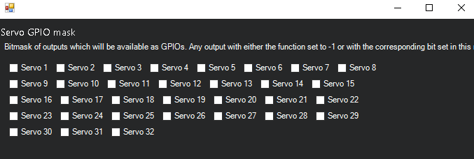
Now I have set the relay switch on the FMU side of the pixhawk. and still it is not working. set the SERVO_GPIO_MASK on SERVO 7 and tried value -1 (when I choose SERVO 7 Missionplanner sets te value on 64…) then I tried it again, but nothing happens. The buzzing noise has stopped when I plugged the switch in the FMU port 7.
I hope you can help me solving this problem.
Kind regards,
Mark
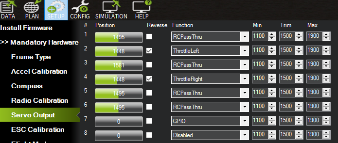
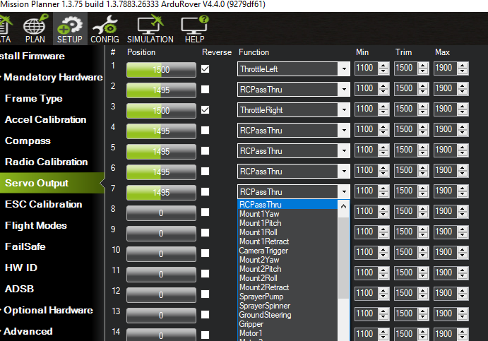
you go to the servo page on mission planner, then set the channel 7 output to -1 for gpio, then set the relay 1 pin to pin 56.
1 Like
Thank you for your reaction!
I think I’ve allready done that… but it isn’t working. Sorry but i’m new with ardupilot and missionplanner. below some screenshots of the settings. Am I missing something?
Use an AUX output starting with chan 9. Some other considerations:
What does this message say when you connect?
![]()
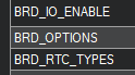
What is this parameter set to?
BRD_PWM_VOLT_SEL
Hi Dave,
Thank you for your reaction. Coming weekend I will take a look and answer your question.
Kind regards
Mark
Hi Dave,
this is where the switching relay is plugged in.
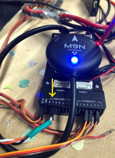
As you can see I’dont have an AUX output starting with 9… so I have plugged it in to no. 7. Reason why I did this is because I want to use servo output no. 7…
I don’t know where I can find the Parameter "BRD_PWM_VOLT_SEL. I tried the full parameter list but it hasn’t got this option…
As said I’m new with Mission Planner so I need a bit more help then the usual user ![]()
Yea you do, it’s I/O PWM out 1
Forget about that, not all FC’s have that parameter.
1 Like
Right, just to be sure that i will set the settings right…
-
I have to set the servo setting to “-1”
-
Set servo GPIO 7 to
 because this is the switch i want to use on my controller
-
Servo settings (7) set to GPIO
Then put the signal cable of the switching relay to the first pin of the I/O PWM Out of the Pixhawk.
The all will work…?
No.
RC7_OPTION, 28 (relay 1 on/off)
RELAY1_FUNCTION, 1 (relay)
RELAY1_PIN, 50 (AUX out 1)
SERVO9_FUNCTION,-1
RC in chan 7 will control relay 1 on Aux1 (chan 9) output.
Hi Dave,
Thank you for your advice. It did not work… i think I’m doing something wrong but I don’t know what.
I have found a pwm switch and managed to get this working. The problem is solved but in an other way then initially thought of.
As sad many thanks for you’re patience.
Kr.
Mark
did you set the jumper on the relay to activate when high?
Did you get 3.3Vout on a voltmeter when you activated the relay?
Did you see CHAN9OUT go high in the Status screen when you activated the relay?
You know, standard isolate the problem troubleshooting.
1 Like