I was wondering what the circles to the left mean, I have looked all over to see if there was an explanation.
I have a presentation and was trying to show how the footprint can change relative to altitude and focal length, but didn’t have a good explanation of what the dots represent.

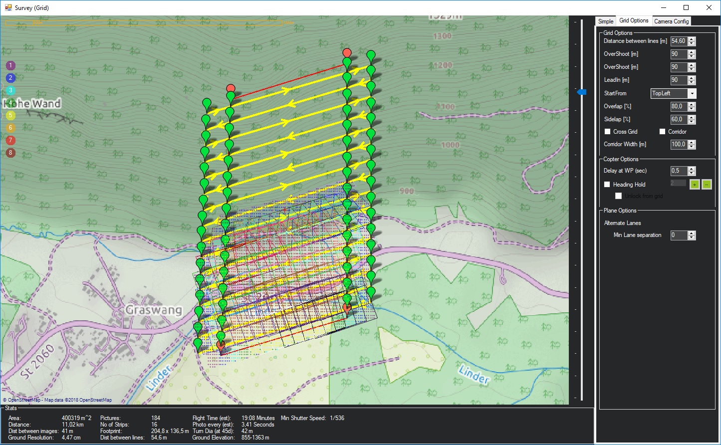
its the number of photos that capture that spot on the ground
Seems to me it works in flat lands, but not in the mountains. There are no foot prints in the higher elevation path.
I was wondering the samething if that is just a projection error on the map or if it is just MP having trouble placing footprints in a basically 3D space? Or is it not reading terrain data and not accounting from the UAV maintaining a specific (± 1m) AGL flight path.
the plot is using above home location. and is showing that you will fly into the hill if you used that mission
Sorry, I should have been more clear. If I plan a mission in the mountains, using ‘Absolute’ + ‘Verify’ Height it doesn’t work - see attached files.
Test_Footprints.zip (907.8 KB)
Shouldn’t also using terrain and verify height set default altitude to 120, shouldn’t that keep it from flying into mountains. I ran this exact mission in real life and it did not fly into the mountain it followed the terrain ± 5m. Michael is it just in the survey data screen that it will not calculate the footprints with terrain?
the survey grid interface was designed when only relative alt options where around.
it needs a overhall to use terrain and absolute.
verify height is a way around this though.
when I choose the absolute altitude are the overlaps calculated from the height in relation to sea level? for example in an area with a SRTM range of 50m - 80m, can I plan on the sruvey grid a flight 150m altitude (70m from the ground) of altitude throughout the area of the map?
Could you direct me to where in the code the image footprints are created?