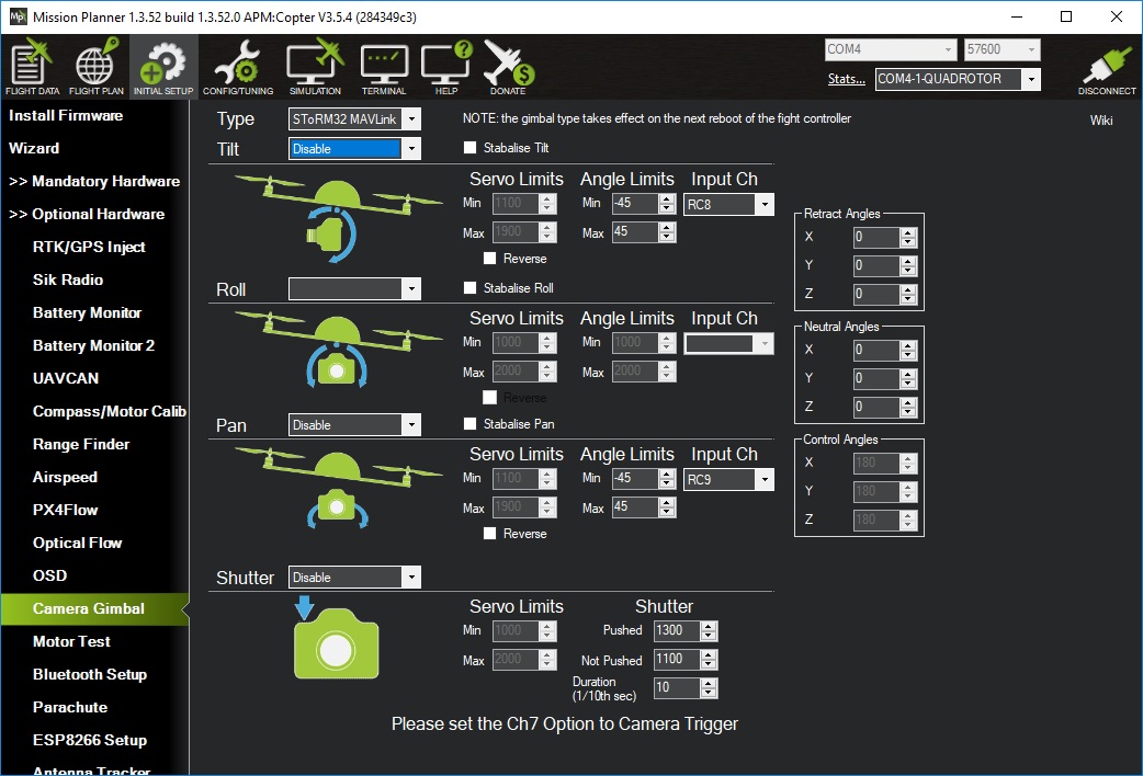
hi @olliw42 , One point is not clear for me. I’m using a Tarot 3DIII with SBus, no problems, I associate RC8 and RC9 in the Tarot configuration software in order to interact with the RC for Tilt and Pan (via sBus). What is missing for me, I applied the instructions from the wiki there: http://www.olliw.eu/storm32bgc-wiki/Using_STorM32_with_ArduPilot#STorM32_Mavlink
and did the wiring like described there: http://ardupilot.org/copter/docs/common-storm32-gimbal.html
So I understand that sBus is a different protocol as mavlink, but my question is: where do I associate in the Olliv’s configuration tool the Input CH RC8 RC9 that I have to type in the MP Gimbal page setup?
in the STorM32 GUI you don’t do anything (except enabling the mavlink heartbeat if using the Mavlink mount)
with these mounts it’s the ArduPilot’s job to translate the incoming SBUS signals into outgoing mavlink messages to the STorM32. That’s what you are setting up in the MissionPlanner screenshot. The STorM32 at no point sees the incoming SBUS (you didn’t connect SBUS to the STorM32, right, only to the ArduPilot).
btw, docs generally have to be read such that if something is not mentioned that this something does not have to be done - so, you found the info in the docs
Ok! Thanks. The only wired link I have now is the Telem2 to UART. But what’s put me in trouble is there: Advanced Functions - STorM32-BGC Wiki
in the experts tools menu: I’ve never find this: Mavlink Com Port: Selects the com port which shall be used for the MAVLink communication.
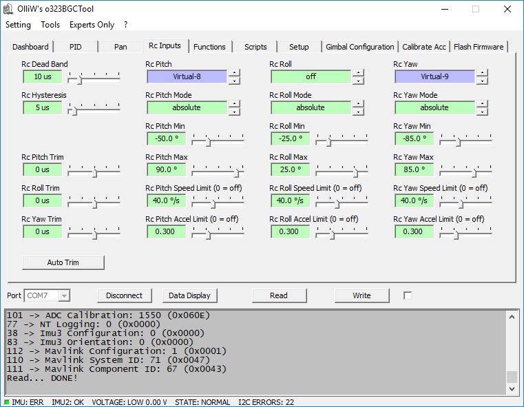
well, you know, there are versions, and it may be crucial to look at that … from the I2C in your GUI screen shot you must be on a dammed old version, such as v0.96 or even below … this is two years old! It’s less well maintained, but this might be the more accurate wiki for your setup: http://www.olliw.eu/storm32bgc-v1-wiki/Main_Page
Sory I’m a very dummy guy in this area, even lost now… but as I have a HAKRC Gimbal Storm32 BGC 1.3.1 board, which is not NT (I presume) and when I click on your link for buying boards, they have the same version 1.3.1, http://www.olliw.eu/storm32bgc-wiki/Where_to_buy_STorM32_boards
So my question, can I upgrade just buying a NT module??? Sorry if the question is stupid…
it’s a valid question
short answer: yes
longer answer: It’s not easy to get NT Imus, you find options in the wiki, such as the Ensys NT Imu, or using a CC3D. In addition, the v1.31 has a power issue in combination with NT, and one is nearly always better of using a v1.3 (you find a comment/explanation in the wiki). So, bottom line, one could be better off with going directly for the 30$ bundle. But mind you, recently some reports appeared where users didn’t got the bundle they’ve ordered. Quite messy situation.
Thanks, find on the wiki for 1.31 power issues: “One single NT IMU seems to be ok” , so in my gimbal I will need only one to replace my I2C, so I presume it’s ok, and I’ve mesasured 3.26V at the I2C wires, so If I find an NT IMU I can try this and firmware to the latest 2.30 in order not to have a 3 years old obsolete solution right?
with the v1.31 only the Ensys or the “olliw-compatible” NT imus are OK, the CC3D has been reported that it may or may not work on the v1.31
the voltage is irrelevant, the limited current it can deliver is the issue
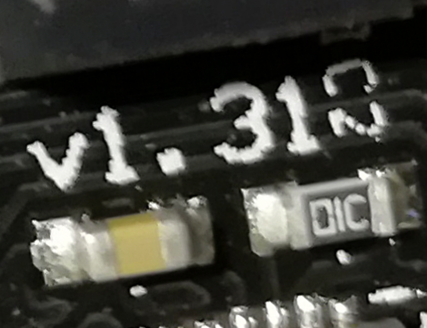
btw, you may actually want to visually inspect the particular board you have
one can’t always trust the printed on labels, so, there are v1.31’s which are actually v1.32’s, and v1.32’s which are v1.31’s, and then there are v1.31’s which are neither of both, pl continue the list of iterations yourself …
it’s easy to distinguish if you have a LDO (=v1.3=v1.32=good) or a switching regulator (=v1.31=bad) on your board
there are also relatively easy fixed for the v1.31 board to overcome it’s power issue, see wiki
so, in short, get yourself a NT imu, and everything else can be worked out
About version, with the config software, it indicates:
v1.30 F103RC . What’s written on the board is 1.31.
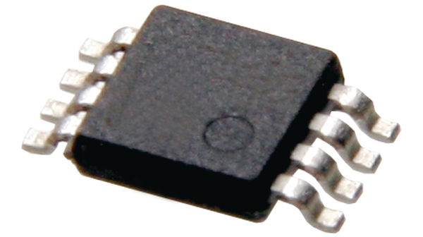
Googeling the number written on the component i suppose to be the regulator (is it this thing?)
44074 I’ve got the reference Texas Instruments 296-44074-1-ND which confirm me that’s a switching regulator. Too bad! So for me the solution would be to use an UBEC for powering it?
Anyway, thanks for good support!
great it’s working
the firmware can’t tell v1.3 or v1.31 apart, so it just tells v1.30 (maybe I should change to show just v1.3)
the part you show is probably the reverse-voltage protection FET, at least I haven’t seen a v1.31 which such a sized SR chip
watch out for the inductor, usually a big grayish cubeish thing, with e.g. 100 printed on