Hello all, I’d like to use the Ardupilot for steering my 31-foot sailboat. I am a newbie in ardupilot but the manuals are great and detailed. Haven’t seen something similar on the forum as most of the projects go with servos or skid steering, so the question is…
Can a 12V DC motor be used for rotating the boat’s steering wheel? 1 pulley on the motor and 1 pulley on the wheel, connected with a belt. All it has to do is rotate CC or CCW, and maybe adjust the speed of the motor according to the error’s value (utilizing the PID in the ardupilot?). The wheel is really light and doesn’t need a very high torque motor.
Is this possible? If yes, what motor driver should be used, and on which PMW pins of the PixHawk should connect?
Thanks
You could probably get away with building your own “servo” really. Dump the normal steering servo/pwm channel into an arduino then build a system that looks at wheel position and outputs voltage accordingly.
just run any “First robotics competition legal” motor control.
Here is a cheap one that also has limit switch provisions built into it, if your into that sort of thing:
Thank you for your reply, Darrel. I also thought that maybe have to get the Arduino in business, but if it’s possible to do the project without it, that would be great since my programming skills are very basic!
Instead of a DC motor, I found a high torque continuous rotation 6V servo that will be powered from a 10Amp DC to DC ( 12 to 6v)converter from the boat’s 12volt batteries.
The servo then just needs a PMW signal from the pixhawk ( ground steering function output?) and as I have understood ardupilot so far, that should be a functional setup correct?
Hi,
you will need some kind of feedback, so the PWM signal from the pixhawk results in a certain steering wheel position. A continuous rotation servo is just a DC motor with ESC and gearbox attached. There is a servo from parallax with a feedback output:
but I doubt it produces enough torque for your application and you would still need the Arduino…
An Arduino is an easy way to build a feedback loop for any kind of drive yourself. It reads the PWM signal from the pixhawk as a setpoint. It also reads somekind of angular sensor (poti is the easiest) as the process variable. A PID loop takes the two values and creates the PWM output for the DC motor/continuous rotation servo. The programming is not that complicated, even I can do it… :-).
What I would do first is to meassure how much force is needed to turn the wheel. I would guess the force required changes with the speed of the boat, or am I wrong? By meassuring the absolute max force, you can then calculate how much torque/gearing you need to turn the wheel.
Hi Sebastian, thanks for your feedback! You really sound like you know what you are talking about, but I am really amature with Arduino programming, I luck the level of knowledge to do this programming, unfortunately.
Do you think it will not work at all without wheel feedback? Or it will work somehow but adding the feedback will make the system better?
My reasoning for making it without a wheel position feedback is as hand steering. You can steer without looking where the rudder is, but you will eventually find the rudder center as the boat goes straight to the desired course. You might zig-zag a little bit but you will find it by looking just the compass or a point at the horizon.
Could we say the ardupilot acts the same and doesn’t care about the wheel position? In this case, the servo would steer the wheel left or right depending on the error. As the error diminishes and the boat comes back in the desired course, the wheel gradually comes back towards the center also, and eventually stops somewhere because the boat is back in course. Since we don’t have position feedback it might stop slightly left or right of the center when the error reads zero, resulting in overshooting. I guess after it overshoots a few times it will eventually find the center as the zig-zag will diminish every time.
I am really a newbie to all this amazing stuff, I really understand it if all this sounds nonsense to you guys!!
Unless your steering wheel is continuous rotation what will the system do when the steering wheel reaches it’s end of travel and the Pixhawk is commanding it to still rotate?
How many turns is your steering wheel lock to lock?
That’s a good question!
It reaches its left-right ends after 2 turns from the center. Thinking that since the boat quickly reacts after 1/4 of a turn, the pilot will never have to keep turning the wheel until the end.
But in case the boat is sailing very slowly and the rudder hasn’t enough water flow to turn the boat, the pixhawk will probably keep turning the motor beyond the rudder ends trying to bring it back on course and damaging the wheel worm gear if one leaves the situation like this.
At this time with no wind a sailboat has to motor to make way and gain steering again
This is a commercial wheel autopilot that works without a rudder position feedback. This kind of system is what i thought could be “copied” with pixhawk. http://www.cptautopilot.com/index.php
I would run it in guided mode 99% of the time, as this is the best way to navigate. Go to one destination waypoint and manually update once there. Auto mode is also great in the way it stores the mission on pixhawk, not needing another consumer such as pc or smartphone/tablet to be active)
Secondary, it would be fun to have manual or acro control of the boat with a remote control. That would help steer from a more protected place not having to get wet on the helm!
Hi Themis! I have purchased hardware for the exact same kind of project. From the available literature I have now resigned myself to the fact that a certain amount of programining will definitely be involved. But you could begin your project with the Helm drive system first and install a simple drive system. For my first step I will be going with a chain drive mounted to the Helm wheel which will be driven by a Nema 24 stepper motor. Which in turn will be driven by Stepper motor Driver( TB6600 Stepper motor driver: See Aliexpress). This is set up that allows for many development possibilities. Firstly, you could control your wheel direction by connecting a ST-PMC1( See Aliexpress) to the TB6600 driver. The ST-PMC1 has direction buttons on its pannel. With this set up you can achieve your minimal objective( Staying dry). After you have this basic set up installed,the controller can be replaced at a later stage with a more complicated and versatile Autohelm system. For example an Arduino Piloting system. But at some stage or other, in order to progress you will have dive into the basics of Arduino or Rasberry PI ( Python) programming. I am in the same boat. I have also purchased an Arduino starting kit. And am looking forward to new horizons. Which hopelly an Arduino based can take me to. On AutoHelm of course.
Hi Raymond! good to know another fellow wants to do it also:)
I started with Arduino last year but really need high-level skills for programming an autopilot in C language. I found coding difficult because from the basics you must dive into much more difficult stuff. I feel there is no middle stage…
Can you describe what doesn’t work for you with Ardurover and pixhawk? That would be great to have ardurover firmwire and pixhawk for this job…
You are right in making the manual drive system first. Thanks for the info on doing it with the stepper motor setup:)
This is the servo i found to drive the wheel , has enough torque for the job and it’s waterproof also. Just needs the PMW from pixhawk and an external DC power
That was a good question about:
Ardurover and pixhawk? The truth is I haven’t looked deeply enough into either of them. Thought both were specific to small low power low weight projects. But have just had a look at ArduRover and am feeling the excitement. Am presently sifting through the details of the ArduRover and see they have since 2018, been doing some great work on sailboat Piloting( Models). Am particularly interested to note that Brushless motor control is part of the system. If Pixhawk can provide the input for my motor driver(TB6600) or similar driver then it seems like the way to go. I think it can. But will have to do some serious further reading and enquiring. Anyway I will have a lot of time to do all the research before my parts come from China. But It’s great stuff to read about and should be a lot of fun and satisfaction. Providing I don’t have to do much programming! How is your Helm drive shaping up? My chain drive will be a 60 Tooth Bike Crank sprocket mounted on a circular aluminium plate screwed to the back of the helms wooden Wheel . The motor drive sprocket size will give a reduction gearing of ca 5:1 giving a corresponding torque increase of the same magnitude( Holding torque of 15NM)So it should win a fight with any Weather Helm. Could be overkill. So might opt for a Nema 23 which will fit better and without cutting into the ships interior and draw less power.
There is no real boat with ardupilot yet, but farmers have done it successfully on their tractors, so why not! Chain drive is a good idea. I will probably lathe 2 plastic ( maybe Teflon) pulleys for a belt connection, to a ratio of 1:4 (approximately)
You have more than enough torque in your design, my motor has around the same torque.
The driven pulley on my wheel will have a stopping torque of 136 kgr-cm or 13NM and a max 15rpm which might be a little slow ( my servo motor is 35 kg-cm 60 RPM). I am not yet sure about a reasonable RPM for the Wheel. Have you thought of that? Think somewhere between 15 and 20 rpm should do the job
I’m not working on a sail boat but I am working on a reasonably complicated boat for environmental and survey work. I think one thing I’ve come to the conclusion on is that the Pixhawk and Ardupilot have a very narrow operating task and scope. It is amazing at navigation but way to much work to interface with additional hardware. I think trying to merge pixhawk with some other control system would probably be way to much work. Building a separate steering system (or whatever custom hardware system) is probably the way to go but if it were me I would interface to the pixhawk via it’s normal Servo channel.
Especially when the stakes get high (ie property damage and loss of life) it might be nice to not push the boundaries in some new pixhawk control scheme.
Also stepper motors are nice but aren’t immune from error. If you motor skips steps because of some obstruction or high load the control system will never know unless you have and encoder built into it.
If you use an Arduino to take the pixhawk servo signal and drive what ever device you build the code may not be nearly as bad as you guys think. You can use “pulseIn” to read what the servo command is.
Yes 90 to 120 degs/ sec sounds fine. But such parameters can quite easily be tuned later in the project. I have spent hours combing the web and am now faced with two choices. The Pixhawk pilot cannot control stepper motors##?!!!Ummmmph! So the choice is either to stick with the Stepper and go with Arduino or Raspberry Pi or go with a Servo and Pixhawk. It is here that I thank you for the Servo idea. Though I will go for a much more robust model. I had doubts at first. Mainly because i envisaged my drive motor revolving multiple times with the Stepper and could not see how a steering servo could fit into my imagined system. But the pixhawk seems to have an output dedicated to steering servos. Which you would expect on a system controlled by ArduRover. I havent looked at the exact details for ArduRover or ArduBoat but It seems clear that the Steering servo motor in both cases is meant to be one of 180-300 degrees rotation controlled by PWR. So that leaves me with a lot more reading to do. I can’t bring myself to give up on Pixhawk now. The system just seems so elegant and robust. So I will step over the mole hill problem of Pikshawk rather than climb the Programming mountain that developing an Arduino autohelm represents( For me). Is your plan to use a servo of limited revolutions(<360 deg) or have you found a solution to allow the servo to complete multiple revolutions? I am thinking of using a very high torque servo of ca 100 to 200kg with a drive sprocket ratio 1:1 or 1:1.5. Hopefully I will be able to find a large drive sprocket for the task. Now I have to look into how the Pixhawk, with the help of a motor driver can up some amps. And perhaps look at some Youtubes on servo control. Thanks for the chat.
Happy new year!
I will use a continuous rotation servo. That means that if the pixhawk outputs pulses <1500μs, the servo will rotate continuously CCW (turning the boat to the left). A normal servo will be at -90 at 1000 μs, centered at 1500 and at +90 at 2000. In previous posts members with actual pixhawk experience suggest that the system might need a wheel position feedback which is very reasonable and an arduino has to be used for this. However there are commercial pilots that run without feedback sensor.
Using a normal 180 degree servo has the actual position feedback built in so this issue is solved. But then it has to work in 1:1 ratio and it will only be able to turn 90 degrees left and 90 right. In my boat thats not enough but it might be ok for yours?
Happy new year! Thanks for your feedback Darell. Have you setup ground or skid steering for your boat?
Being on board makes things much easier. Sailboats go slow, and someone always is on watch, so if just disengage the drive pulley with a clutch you have the boat on your hands immediatly.
Do you have a thread for your project? Sounds very interesting!
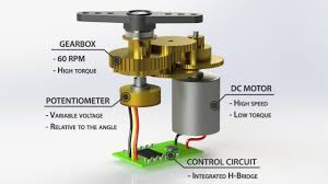
Happy New Year T. Yes the limited rotation of the Servo poses a “bit” of a problem. I’ve been looking at high torque motors up to 500kg cm, that can rotate a well controlled 300 degs or so giving 150 in CW & CCW. A 1:1 drive sprocket ratio offers a reasonable freedom of auto controlled steering. So 1:1.5 would be better. However, have found a big problem with sprocket sizing: The inverse relationship between sprocket radius and supplied torque. Even with a 500kg/ cm torque motor. For every cm of sprocket radius the torque delivered is halved. Even a drive sprocket giving 1:1 would approach zero torque at the dimensions I was thinking of. So the typical position controlled servo is out. So thank you for your ideas on the continuously rotating servo. It is the way to go. However, you have identified yet another potensial project stopper: the possible need for positional feedback. Which the Pixhawk does not cater for. But like you suggest, this could potentially be solved by the incorporation of an Arduino. But this approach defeats the objective of limiting the need for : additional Programming. I have been looking at commercial autopilot motor drivers. Most of them seem to be run without rudder sensors. Particularly the Tiller Pilots. The feedback in their case is provided mainly by directional sensors( GPS & Compass) telling the servo to turn on, change direction or hold: The whole point of AutoPiloting. The only occasions, me thinks, the open running servo would pose a problem is the case when the boat is moving too slowly or not at all: as when caught in Irons. With no water moving across the rudder, the autopilot feedback would be unable to correct the boat’s direction and attempt to drive the servo continuously in one direction in order to do the impossible: Get back on a heading. But in such situations why would one have the Autohelm on in the first place. So the need for feedback only really arises when the boat is not moving or moving too slowly. In my case this could only happen if I was sleeping. Since my electric propulsion is always on standby. So I am not really worried about the need for hard wired positional control of the steering servo. The Pixhawk hardware and its ready written ArduRover/ Boat software are so reasonably priced and sweet that I am willing to accept and try to attenuate its possible limitations. Any system that can auto and radio control almost any moving object, from cars, boats, submarines, helicopters and Aeroplanes, is more that adequate to turn the rudder of a boat and steer it. So thanks to you I have now found the way to procede. And I would need a mega sized Sevo to do it. Just a really robust low powered continuously revolving one should do the trick. However I will look into the positional control problem further. The PWM signal from the Pixhawk, like all other PWM drive signaling for Servo’s, is basically, like you say; a 3 signal system: One for rotate CW, another for rotate CCW and the stop signal. I will now search for info on possible parallel circuitry for the Pixhawk servo drive to see if its possible to connect an electronic or physical breaker that decouples the Servo when the Boats helm has reached its limit: A limit switch of some kind. Anyway T, I appreciate your feedback. It’s got me back on course: Chain Drive by Servo, Pixhawk plus external Servo Drive and limit switches. Ok!!! Have just watched YT : “How Servo Motors Work & How To Control Servos using Arduino.” From their diagram of a closed loop servo we see that the range of rotation of the stepper is controlled by potentiometer circuit: