How did you guys manage to distribute power from the battery to multiple devices? (Pixhawk, camera, ESC)
I have found no solution without having to rely on breadboards.
I have an 18V battery, I will use a 5v power regulator for the pixhawk, a 12v regulators for the ESCs, and 5v regulator for the camera, but I have no idea how to connect everything without using a breadboard. I have looked up terminal strips, but have no idea how to build a circuit with it.
This is my first project that is not a pure arduino + breadboard project. I am quite stuck and confused
Seems like a capable PDB plus a lot more. And yes, this one you certainly can use. For some boats I have used a PDB. And then I distribute out to consumers from the GND and B+ (assume it is short for Board +). This board has a whopping 8 of them.
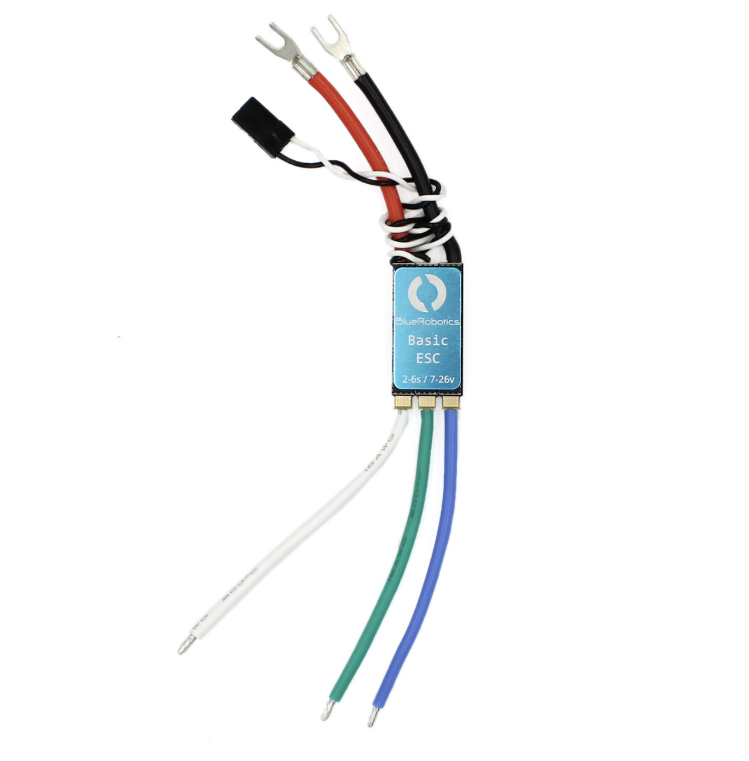
For the ESC you cut off the provided connectors. Maybe also solder in some extension wires if the distance to the motor requires it. And then solder on to a pair of GND/B+ of choise.
It includes a 3A 5V BEC as well, you can use that for the Pixhawk servo side power and/or the camera (depending on power requirements of the Servos connected) and perhaps leave out a separate BEC. And then follow the instructions available on a link in this page for how to power the Pixhawk itself (using the pixhawk power in socket).
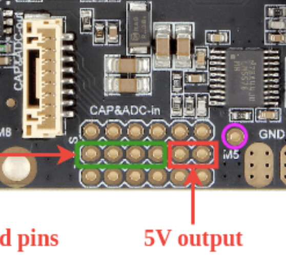
I assume the two ports in the middle are +, and the bottom ones are are - (not sure)
I have never soldered before, so I dont know what the “standard” method is. If I have a USB powered camera (5V). Do I just cut a usb cable, and solder it to the board?
Yes, you can use a suitable. USB cable and cut it off. The first half of this YouTube video explains the details. In short, the power wires inside the cables are usually red and black. And with a multimeter at hand you will get it right…