
Hello,
Been taking on an effort to develop a Simulink blockset which recreates the arduplane control system for use in a flight simulator. The premise is to use mission planner as a command and control system for the simulator via UDP connection.
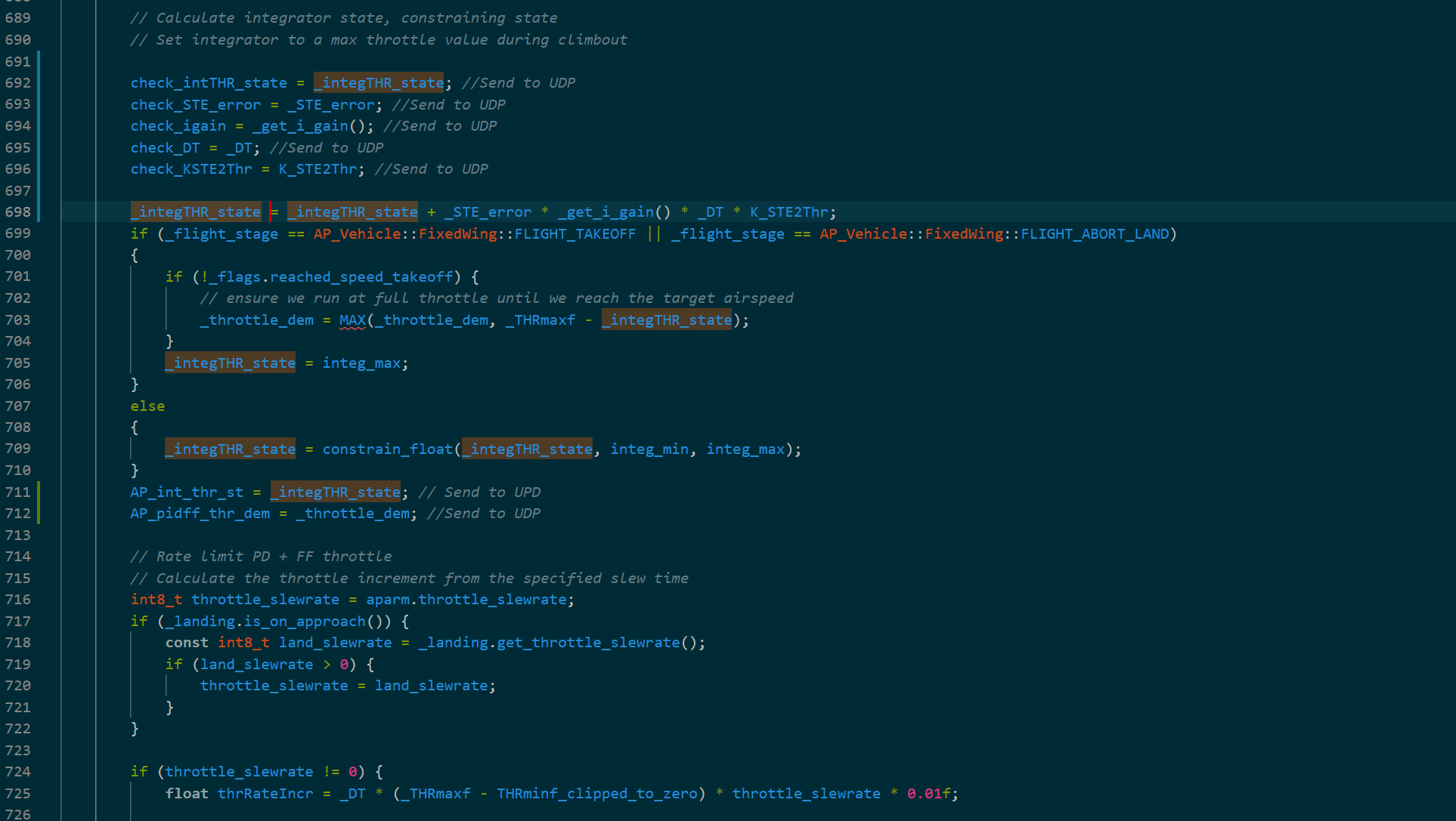
I’ve managed to find the pictured section of the TECS.ccp which cannot be mathematically recreated in Simulink and would like to see if anyone has deeper insight into the TECS controller.
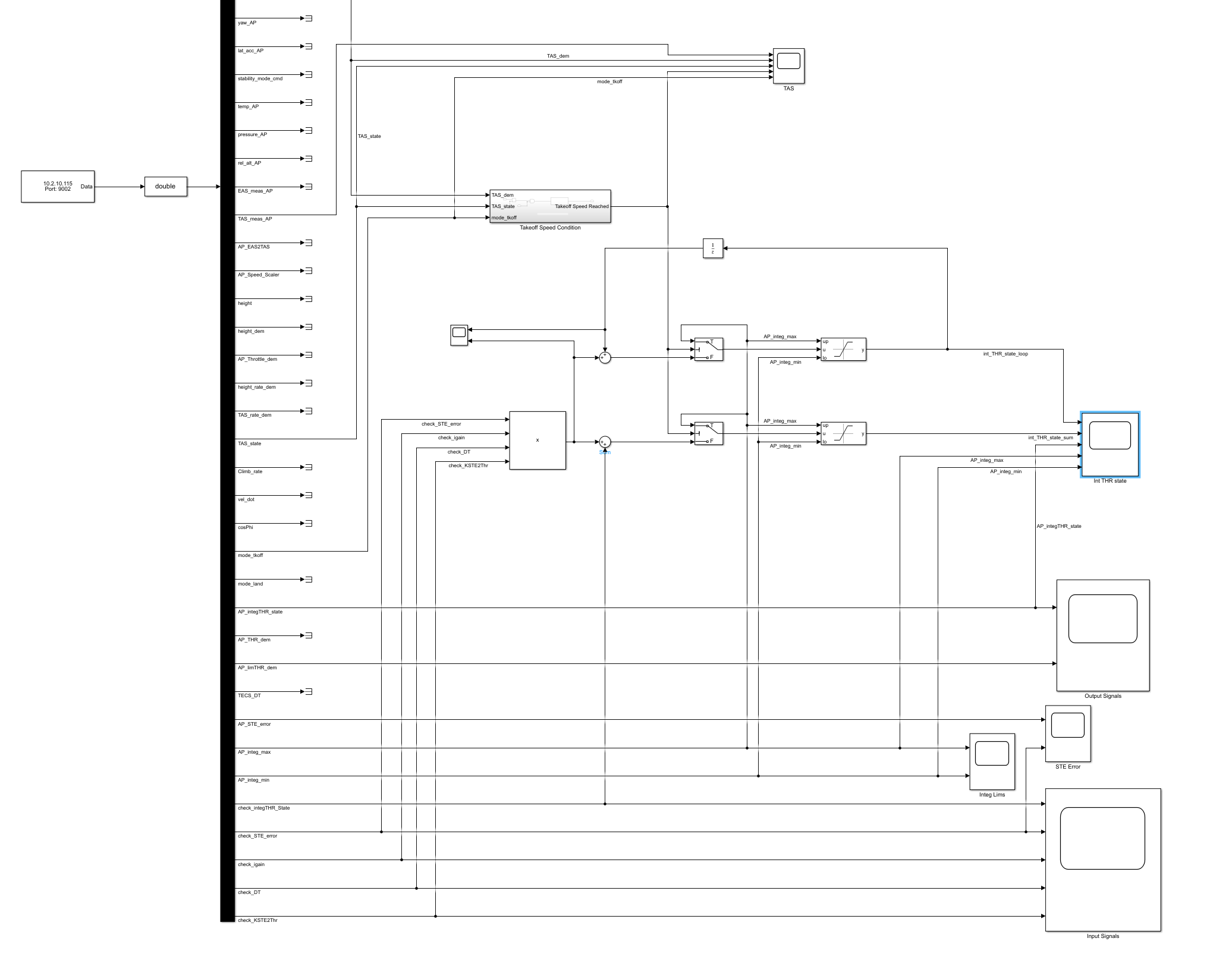
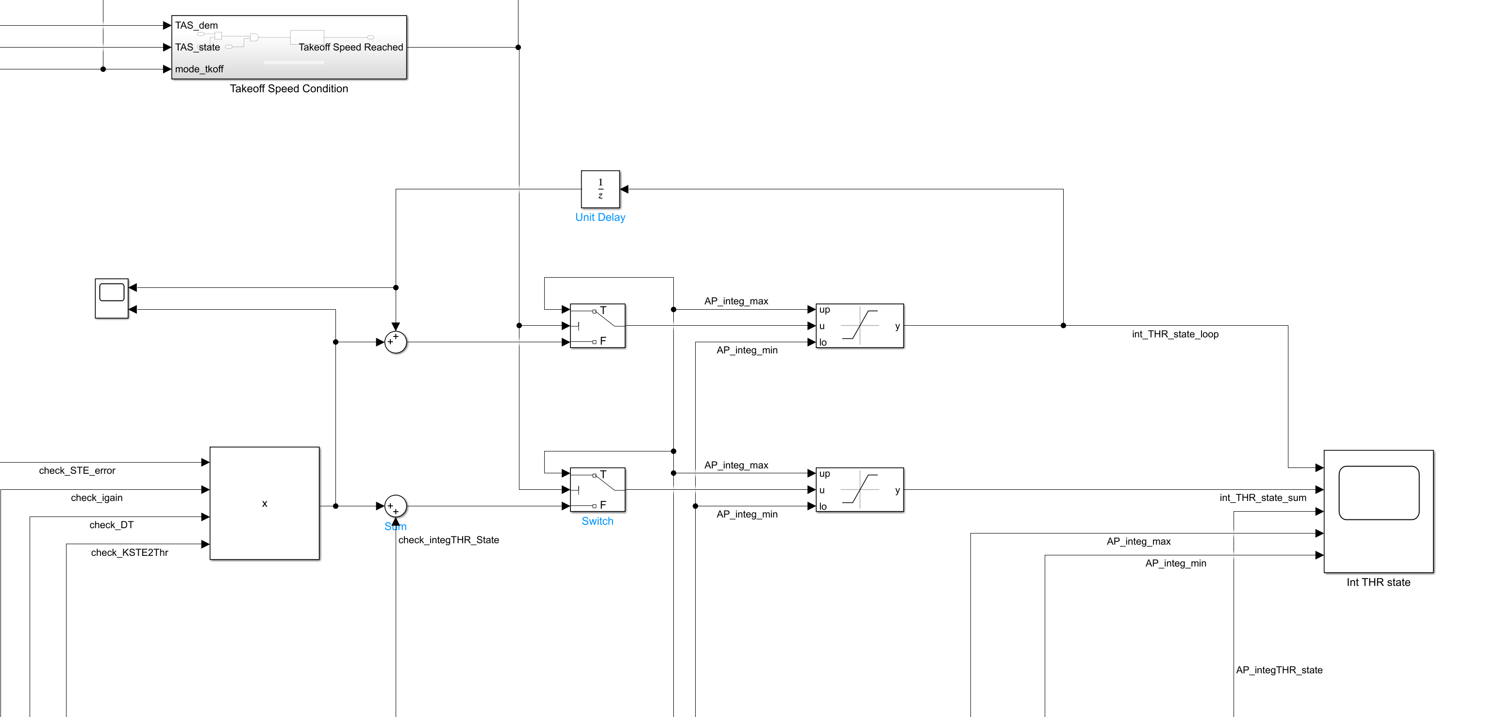
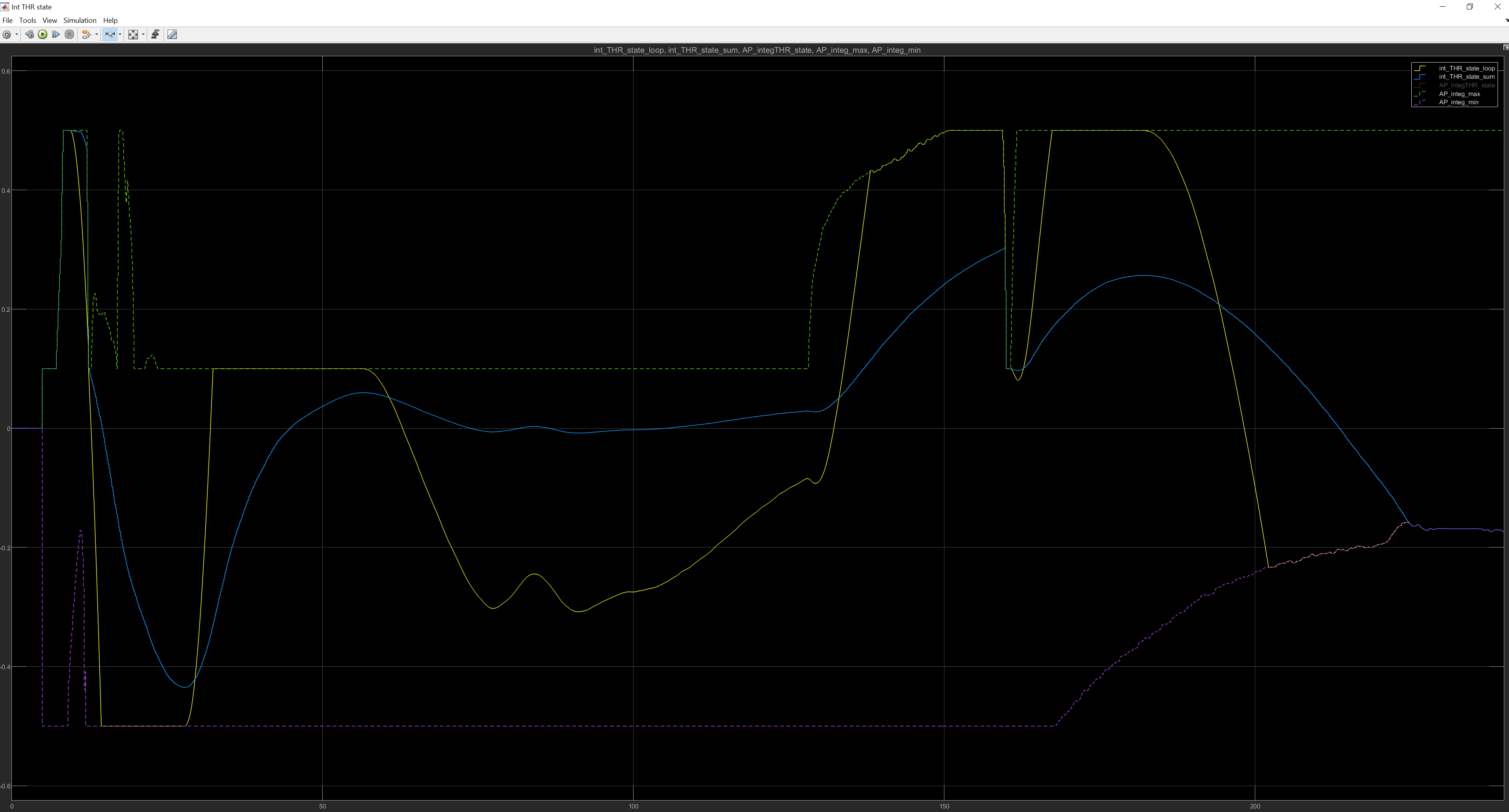
Using the variables pulled directly from the source code in conjunction with SITL over UDP into simulink, we can observe the variables from the TECS source code. I have found that the previous step of the integrator throttle state when added in a mathematically equivalent loop as the source code results in an integrator throttle state which is not equivalent to the result from the source code itself. However, when adding the previous step (directly from UDP) in a '“feed forward” manner the result is consistent (orange and blue signals in plot).
Observe the simulated loop (yellow line) which is much different resulting from a difference in the previous time step of the integrator throttle state. Nonetheless, after looking through the data exhaustively, the difference added from the previous time step appears to be mathematically correct and I have not been able to successfully recreate the result from the source code as it is written. (Is the source code not functioning correctly???)
Note the integrator throttle state is only defined in the source code which is pictured.
In my throttle controller (not pictured), I have recreated and validated all of the inputs to the throttle integrator calculation and am seeing the same result.
Happy to have a much more in-depth discussion regarding the topic, there is obviously a lot more information than I can feasibly share in this initial posting.
Best,
Brett Erickson