Set up of collective and throttle channels

Hi Bill,

I would greatly appreciate it if you would read through my post in more detail and indicate-me some issues you suspect with my set up of collective and throttle channels.

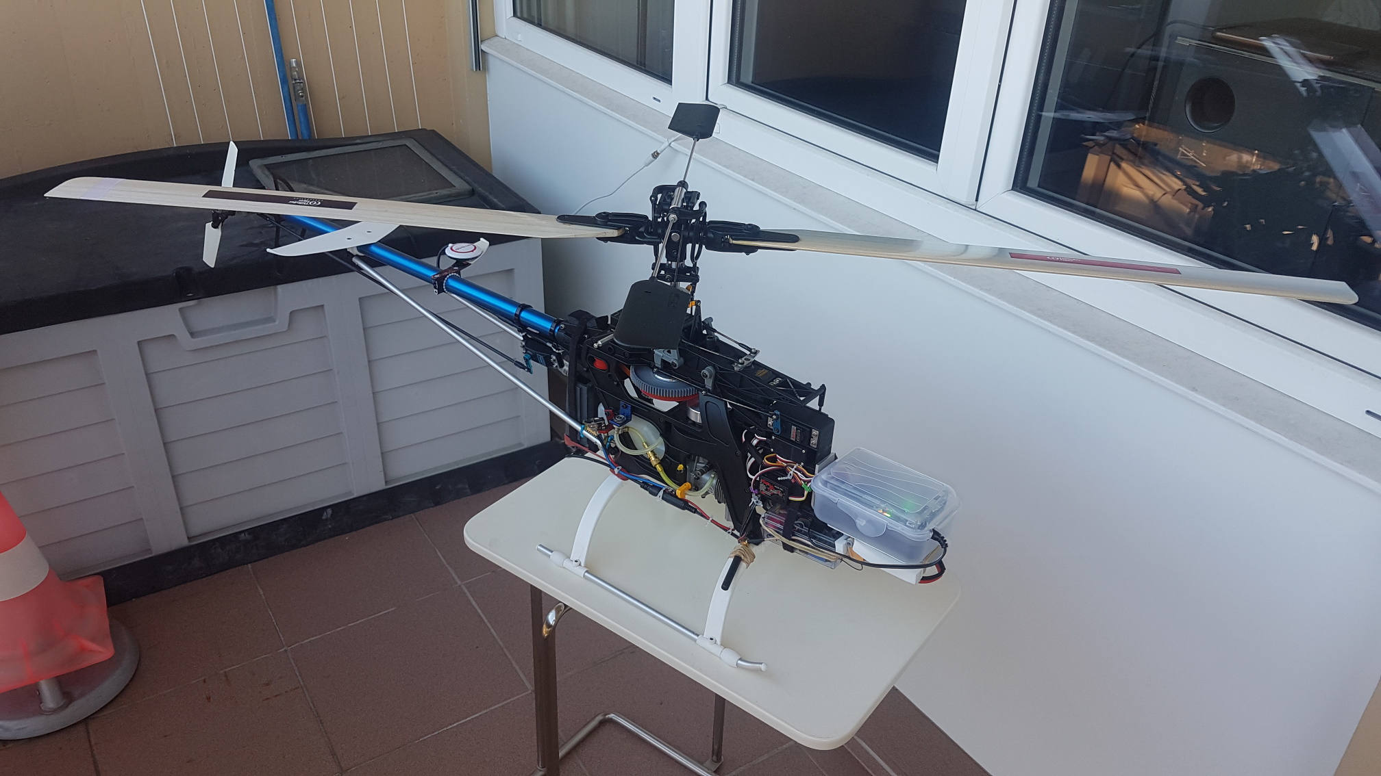
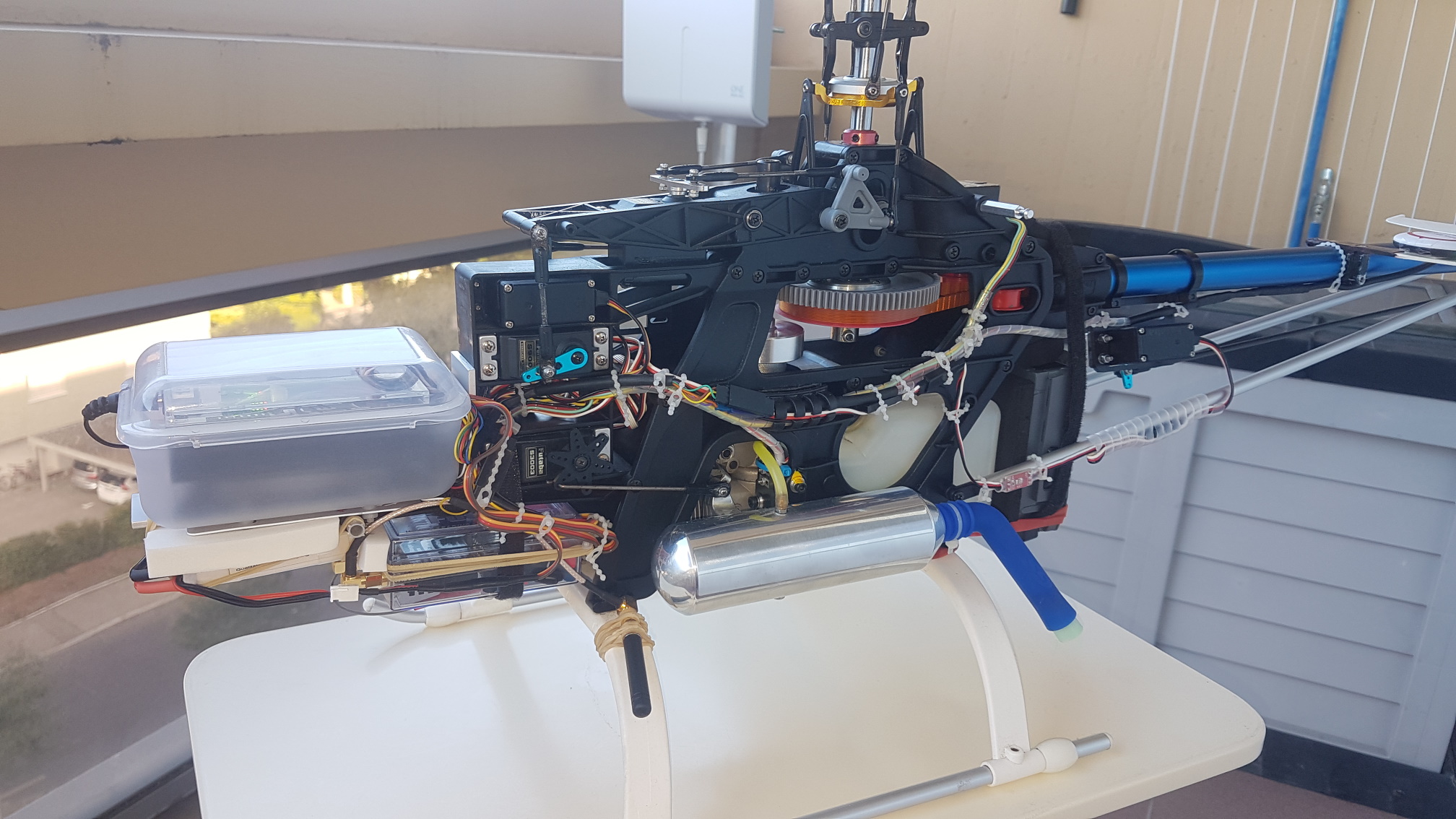
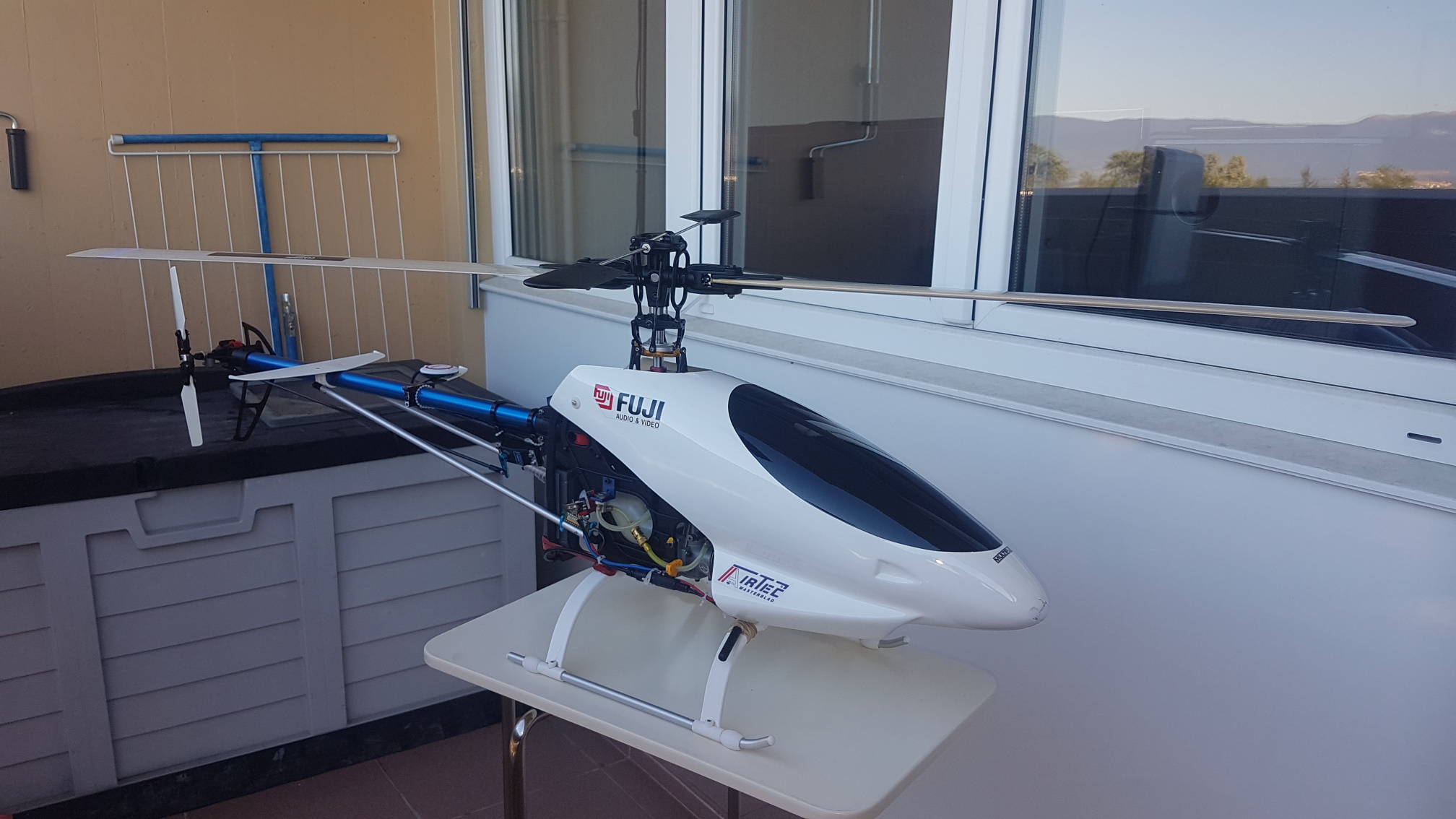
The helicopter is a nitro engine vintage helicopter (Raptor 30 v1).
At the moment, the flight mode is fixed on “Stabilize”. In the current setup the flight mode can be only be changed from the GCS (ground control station). I think this is not a problem for the time being, as I’m still in tuning phase. Once the tuning in “Stabilize” mode would be achieved, the tuning knob would be reassigned to flight mode.

This is how my RC Radio is setup:

  • RC Channel 1 - aileron (roll control)
  • RC Channel 2 - elevator (pitch control)
  • RC Channel 3 - throttle (linear curve between stick and throttle); there is a “throttle hold” switch on the radio preventing the throttle to rise accidentally
  • RC Channel 4 - rudder (tail rotor)
  • RC Channel 5 - in flight tuning (tuning knob)
  • RC Channel 6 - collective pitch (linear curve between stick and collective pitch)

It’s more or less based on the recommendations from Chris Olson’s ArduPilot TradHeli Setup, Video 4.

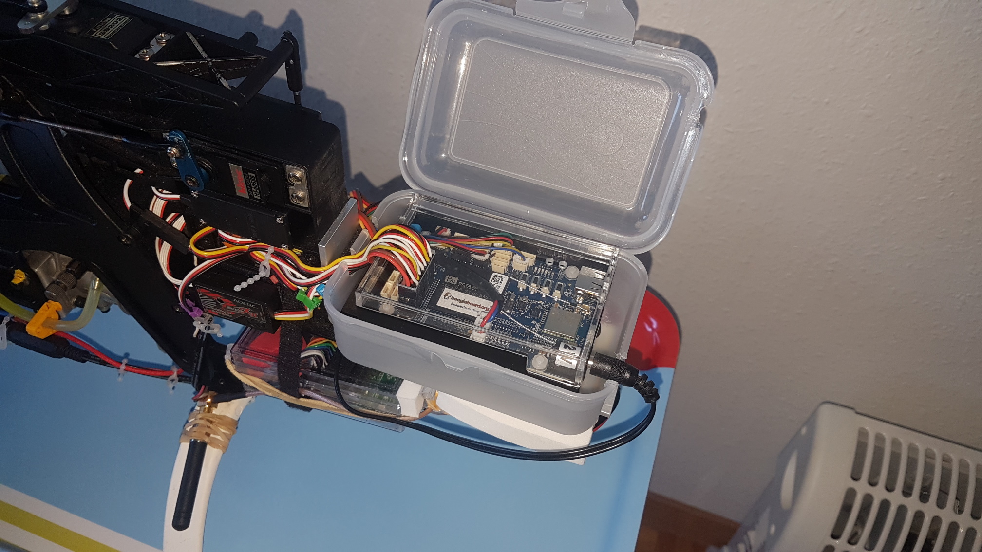
This is how the flight controller is set up:

On the receiver PWM output, is a PWM → SBUS converter. Some PPM wires are swapped (remapped) like this:

  • RC Channel 3 → RC Channel 8
  • RC Channel 6 → RC Channel 3

The Rotor’s Speed Control mode is: “Throttle Curve”
The Throttle Curve is: 25, 50, 60, 70, 100.
The Stabilize Collective Curve is: 0, 52, 62, 100.

And for the servos functions:

  • Servo 1 - Motor1 - aileron (roll control)
  • Servo 2 - Motor2 - elevator (pitch control)
  • Servo 3 - Motor3 - collective pitch
  • Servo 4 - Motor4 - rudder (tail rotor)
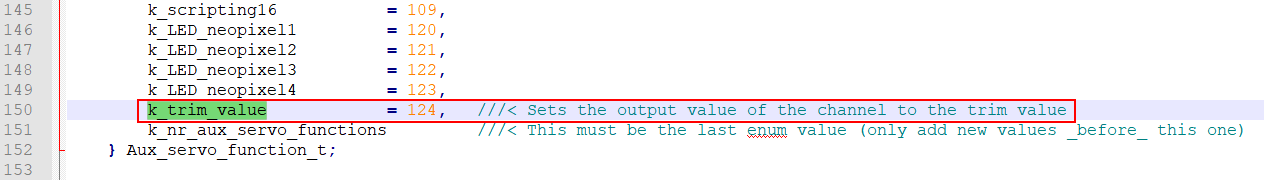
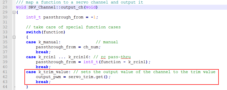
  • Servo 5 - Trim value - governor setpoint (constant function, NEW)
  • Servo 6 - RCIN5
  • Servo 7 - not used
  • Servo 8 - HeliRSC

Remark: Instead of setting Servo 6 to RCIN5, it might also be wire-swapped.

The GCS communicates with the flight controller with a RFD 868x Long Range Telemetry Modem (I use WiFi as backup link). If I really need a supplementary channel, it might be possible to use the RFD 868x PPM Passthrough (making a PWM to PPM converter with some Arduinos Nano).

I already flown the helicopter in a similar setup (excepting that RC Channel 5 was the governor setpoint in RCPassThru mode).

Unfortunately, by trying to find the optimal tuning, I had a small crash. After analysis I found:

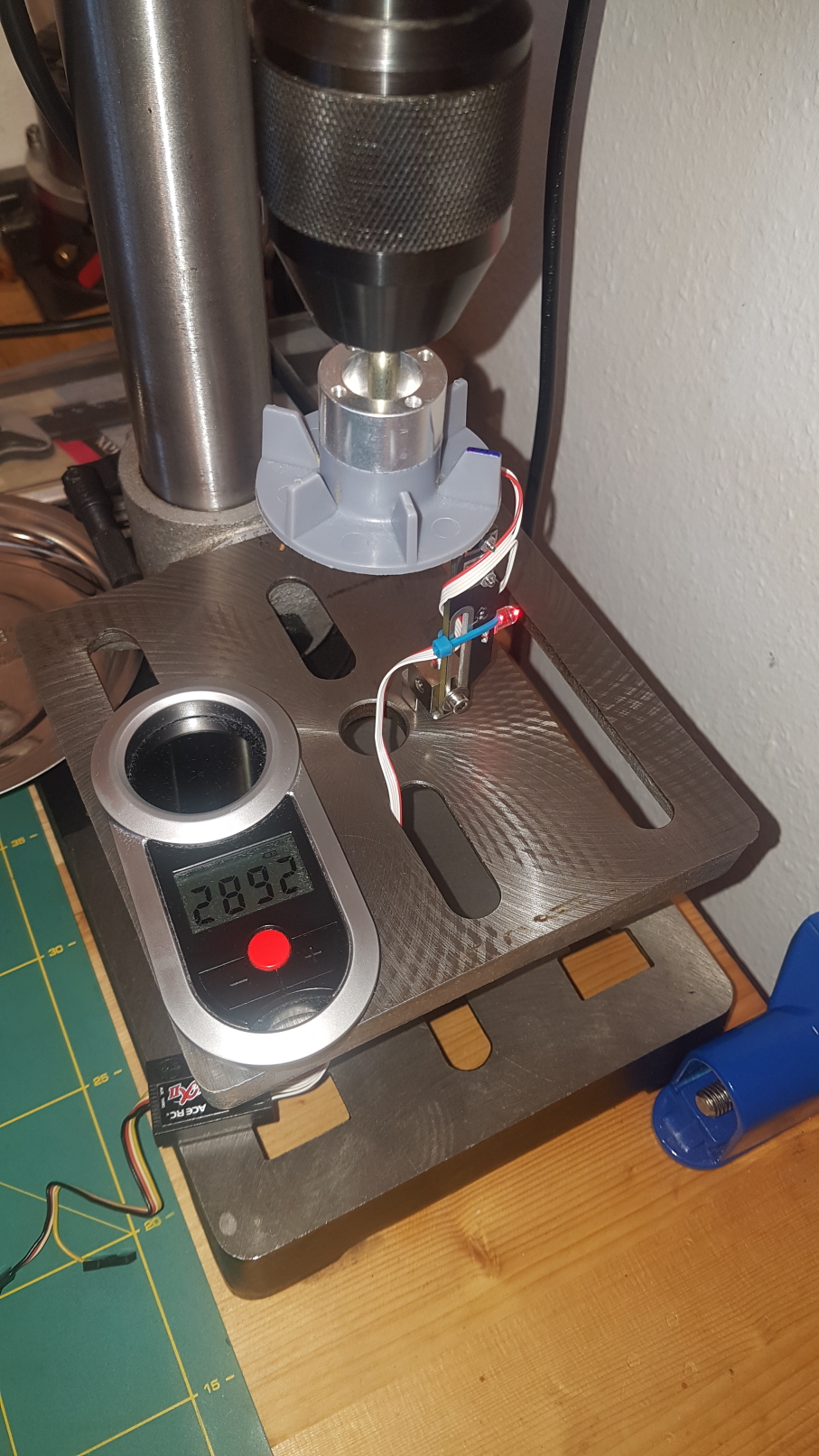
  • Excessive vibrations
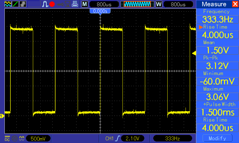
  • Bad dynamic response of analog servos at RC_SPEED 125 Hz (only the rudder servo is digital)
  • The necessity of a button to tune from the radio: in case of a dangerous tuning range, the pilot can immediately turn the knob back and land the helicopter safely.

Therefore, for the next flight the following steps are planned:

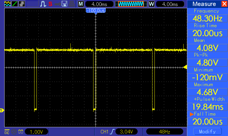
  • Set the RC_SPEED 50 Hz for all servos (done)
  • Increase the flight controller suspension damping: make the shock mounts softer (done)
  • Make tuning from the radio (done in my own version)
  • Analysis of the Shock Response Spectrum (SRS) - we suspect that the box of the flight controller might induce some resonance frequencies
  • The helicopter will be first flown in manual mode (RCPassThru on channel 1, 2, 3 and 6 + radio throttle curve set to : 29, 45, 60, 72, 100). In this phase, the vibrations levels will be registered and analyzed
  • If vibrations levels are acceptable, then the manual mode will be disabled (cancel RCPassThru) and in-flight tuning of PIDs would be done from the RC button (tuning knob)
  • Once the tuning achieved in “Stabilize” mode, the tuning knob channel would be reassigned to flight mode

Thank you
Vlad

@dorovl please post a param file as well so I can look at your set up in detail.
Thanks
Bill

This is not a good set up of your transmitter. In your transmitter, what is the vehicle type that it is set to? Typically they have an airplane, heli and maybe sailplane. I have mine set up to airplane as a vehicle type. The reason I do this is that Arducopter can handle all of the heli functions that you use to need in the transmitter. So all the transmitter is needs is to provide output for the joysticks, a switch for the motor interlock, and a switch for the flight mode. That is the bare minimum. So the transmitter does not need a heli configuration. Thus your connections can be ported straight through from the receiver to the flight controller. No need to swap channels as you indicate here.

Not sure why you have the throttle RC channel 3 being fed to Motor interlock (channel 8) especially if you are using RSC mode 3 (throttle curve). In fact I would recommend getting rid of the PPM encoder. It is one more thing that can break. Plus I don’t trust them. Get a receiver that is SBUS compatible. I can get a Futaba SBUS receiver for less than $100 USD. I think they are more like $70.

What is the point of passing through RCIN5? What does that have to do with tuning? Do you have an external governor on this heli and that is why you have servo 5 set to a governor setpoint? ArduCopter 4.0.3 has a built in governor. It is RSC mode 4. I can get you more info on it if you are interested in using it. It would make the extra channel outputting trim not necessary.

Hope this helps. Please post your param file so I can take a look at it.

Regards,
Bill

Hi Bill @bnsgeyer,

First, I wanted to tell you that I really appreciate the chance that an expert of your level looks at my problems! My equipment is not the most efficient nor modern. But the initial challenge that I set for myself in this project, was to do as much as possible with what I already have: an old Raptor 30 v1 helicopter, an old FlySky FS-T6 transmitter and receiver, a BeagleBone Blue, a external governor already fitted.

As I’m ok with electronics (was my basic training) I use sometimes an oscilloscope or soldering iron to do some small hacks (for example here: BeagleBone : Faulty PWM output after few flight controller restarts due to wrong IEP Timer configuration by dorovl · Pull Request #13814 · ArduPilot/ardupilot · GitHub or RCInput_RCProtocol : SBUS not working if DSM2 specified · Issue #12743 · ArduPilot/ardupilot · GitHub).

In fact I take more pleasure to understand and solve a problem by my own, rather than buying something already ready-made, which certainly might work better. Nevertheless, if this project will work, I would build a helicopter with, this time, the most modern equipment!

This is not a good set up of your transmitter. In your transmitter, what is the vehicle type that it is set to? Typically they have an airplane, heli and maybe sailplane. I have mine set up to airplane as a vehicle type. The reason I do this is that Arducopter can handle all of the heli functions that you use to need in the transmitter. So all the transmitter is needs is to provide output for the joysticks, a switch for the motor interlock, and a switch for the flight mode. That is the bare minimum. So the transmitter does not need a heli configuration. Thus your connections can be ported straight through from the receiver to the flight controller. No need to swap channels as you indicate here.

In the transmitter, I had configured a “helicopter” vehicle with a linear throttle/pitch curve. Having been on 2-3 forums, I had mistakenly understood that the name “Motor interlock” is just a substitute for “Throttle hold”. Thanks to you, I realize now that Ardupilot manages the throttle entirely.

I will therefore migrate everything in “airplane” configuration following to your recommendations!

Not sure why you have the throttle RC channel 3 being fed to Motor interlock (channel 8) especially if you are using RSC mode 3 (throttle curve). In fact I would recommend getting rid of the PPM encoder. It is one more thing that can break. Plus I don’t trust them. Get a receiver that is SBUS compatible. I can get a Futaba SBUS receiver for less than $100 USD. I think they are more like $70.

I understood from Chris Olson’s videos that the Throttle must be on channel 8. Either things must have changed since, or it was a misunderstanding (my English level is average). I will remove these unnecessary channel swapping ASAP.

Small wish meanwhile: I would have liked to be able to increase the throttle, independently, with a collective pitch close to zero, in order to test the nominal speed of the governor and but also the good adjustment of the nitro engine (the mixture) at ground (as I do on the Guimbal Cabri G2). Is there a way to do that?

What is the point of passing through RCIN5? What does that have to do with tuning? Do you have an external governor on this heli and that is why you have servo 5 set to a governor setpoint? ArduCopter 4.0.3 has a built in governor. It is RSC mode 4. I can get you more info on it if you are interested in using it. It would make the extra channel outputting trim not necessary.

Yes, I already have an external governor mounted on this helicopter, any I maybe for this kind of old machine it’s not so bad like this? If you think that the “throttle value” function has no added value for most users, I will keep-it just for my own and will close the pull request.

I think it would be interesting to use the Programmable Real-Time Unit (PRU) of the AM335x BeagleBone’s CPU to decode the frequency of the pulses generated by the Hall Effect sensor of the external governor. This hack would not require any additional hardware and is a quite an interesting topic, but first, my the helicopter must fly.

Hope this helps. Please post your param file so I can take a look at it.

I attached here the current parameter set, but maybe it’s better if you have a look once I would migrate these parameters to the “airplane” transmitter configuration. It should not take long!

Raptor30v1_stage4_v4.0.3.zip (6.0 KB)

Thank you!! :slightly_smiling_face:

Regards,
Vlad

Thanks for the kind words and I am happy to help when I can.

I understand your goal of trying to do the most with what you have. The code has changed a lot with the release of arducopter 4.0. Which should help out in your case. It now supports the motor interlock on any RC channel as long as the function is specified. The built in governor is new and from what I’ve been told it works quite well. For the Governor, you need to set up the rpm sensor feature already built in to arducopter. So you could use the Hall effects sensor and connect it to a servo port and the flight controller can read the rpm.

Currently there is no way to do what you are asking. I would have to think how to safely implement this. Especially if you want to do this with out using an additional RC channel. I don’t think there is a way to do this with out using another channel. I would eventually want to get the RSC working better with internal combustion engines but that is lower on the priority list.

Now that arducopter has its own governor, I don’t see the value in this.

I don’t see the value in this except for your own personal project. Arducopter already supports using Hall effect sensors to measure speed.

I will look at your param file and write more later.

@dorovl I looked at your parameter file. Aside from the servo and RC channel set up, you have
ATC_RAT_RLL_P and ATC_RAT_PIT_P equal to 0.08 and ATC_RAT_RLL_D and ATC_RAT_PIT_D equal to 0.001. Are you confident that these wont cause the aircraft to oscillate. The P gains seem pretty high for a heli especially in roll.

Dear Bill @bnsgeyer,

I applied the settings advised here but QGdroundControl informed me that these settings were out of range and that forcing them was dangerous. By supposing that the doc was not necessarily up-to date, I naively applied the closest limits:

I went through the settings one by one, and corrected them accordingly:

Luckily, you had the presence of mind to check-them, which saved me another crash! :+1: :helicopter:

I will continue with the setup and will keep you in touch!! :grinning:

Best regards,
Vlad

PS: Maybe it would be fine to specify on the doc that the GCS warnings should be ignored.

Vlad,
Thank you for bringing that to my attention. I will put in a change to fix that.

Hi Bill @bnsgeyer,

Before the new the setup I wanted make a precise inventory of what currently exists and/or works for the internal governor (i.e. governor managed by Ardupilot) on the BeagleBone Blue running Debian.

While there are other Linux single-board computers available on the market, the BeagleBone Blue platform has one key differentiator: the board’s microprocessor contains two additional on-chip microcontrollers that can be used for real-time interfacing, an area in which other Linux SBCs have significant difficulty.

On the BeagleBone Blue running Debian there are basically three methods to measure the speed of a rotating machinery with low CPU overhead and fast response time:

  1. PRU (Programmable Real-Time Unit) using Enhanced Capture (eCAP) Module. This technique allows to measure signals with 5ns accuracy without any CPU overhead. I believe that this is a must and only FPGAs can do better.

  2. A GPIO pin can be used conjunction with kernel interrupt requests. However, on Linux, the module receiving the interrupt requests must to run in kernel space. This works fine for relatively low frequency signals and low accuracy (typically the governor).

  3. As an alternative (to method number 2), there is a solution involving Linux sysfs polling in combination with callback functions and POSIX threads. sysfs is a memory-based file system that provides a mechanism to export kernel data structures, attributes, and linkages to Linux user space. Compared to the previous solution, it presents the notable advantage to run in user space while having a great Linux portability (to the detriment of a slightly worse response time and a little CPU overhead).

Initially, because I don’t saw any PRU-based implementations for the governor, I made the assumption that the governor was simply not implemented on the Blue. Although, after some recent checks, I thought that it might work with method 2, I finally realized that it’s really not implemented. Indeed, on this board, a call of “hal.gpio->attach_interrupt” method of AP_RPM/RPM_Pin.cpp leads to an unimplemented “attach_interrupt” method of AP_HAL/GPIO.h returning “false”. I suppose that, since the autopilot is running in user space, one didn’t find a straight method to use the kernel interrupts from this space.

This also affects the following boards: HAL_BOARD_SUBTYPE_LINUX_PXF, HAL_BOARD_SUBTYPE_LINUX_ERLEBOARD, HAL_BOARD_SUBTYPE_LINUX_BBBMINI, HAL_BOARD_SUBTYPE_LINUX_BLUE, HAL_BOARD_SUBTYPE_LINUX_POCKET.

Based on the code provided by Prof. Derek Molly in his “Exploring BeagleBone” book on chapter 6, I have done a test implementation using the method number 3. Here attached is my code (draft) and some tests results: BBB_gov_draft.zip (6.5 KB)

Below is a 333.3 Mhz signal from my function generator, simulating the governor’s signal:

Here the display of the result in the example program:


Note: In order not minimize the CPU overhead induced by the display, the display frequency has been reduced by a 10 factor (every 1 second).

Finally, one can see that the CPU overhead of this program is relatively low (~10%):

I suppose that this code would work fine on HAL_BOARD_SUBTYPE_LINUX_BBBMINI, but I have some doubts about the other boards. If you are interested, I can make a pull request of this code and/or develop a governor module based the PRU (I already did something very similar).

Maybe that, for my project, in the short term, it would wiser to use the external governor as this code is not fully tested?

Regards, Vlad

@dorovl this is beyond my capabilities. @tridge would be better suited to answer hardware questions and hardware interface.

Edit: just want to add that the internal arducopter governor for heli’s uses RPM1 as input. So however you choose to determine RPM with your hardware, make it available under RPM1. Hope this helps.

@tridge could you comment on what options are available on the beaglebone to calculate RPM using the RPM library?
Thanks
Bill

Hi Bill @bnsgeyer,

Yes I used RPM1 as an input. I first I made a debug of the flight controller to see what’s going in the code. I noticed that there is an example named RPM_generic. The examples use the same code as the flight controller and allow to individually check a particular feature. Also, changing something in an example is simpler, the debug is easier and the compilation quicker. If the example works, it should also work in the whole flight controller.

I almost finished the setup with the external governor. It would be great if you could kindly have a look on my settings before the flight scheduled this week.

I also realized a small governor test bench with the help of a bench drill:

I checked the RPM speed with the help of a stroboscopic LCD tachometer. I will also check the Hall effect sensor’s output signal level and frequency with an oscilloscope. Because the BeagleBone GPIO pin supports max. 3.3 V input voltage, a logic level converter might be required.

Regards, Vlad

Great! I am glad you were able to do this.

I can look at it. But you will have to give me details on the aircraft as far as the type of engine and the governor are using. Specifically I would like to know if it is electric or internal combustion engine. Also please let me know if this is a flybarred or flybarless helicopter

Hi Bill @bnsgeyer,

Below are some details about the machine:

  • The flight controller is a slightly modified arducopter-heli Copter 4.0.3 running on BeagleBone Blue boad

  • The aircraft is a vintage Thunder Tiger Raptor 30 v1 helicopter, having a nitro internal combustion engine

  • This helicopter uses a Bell-Hiller type flybar mechanism

  • The engine is a Thunder Tiger PRO-36H (0.365 in³, 1.0 bhp at 14500 RPM)

  • The governor is a Thunder Tiger ACE RC Zero α II using an ATS137 Diodes Incorporated single hall effect switch. The switch turns ON (low) if the south magnetic flux is larger than the operation point and turns OFF (high) whenever the magnetic flux is removed or lower than the release point.

Below are some measurements made on my test bench:

Note: only one south oriented magnet is required; if a second magnet is mounted for balance, it must be necessarily north oriented.

Thunder Tiger recommends a nominal rotor speed of 1400 - 1500 RPM. However, some “experts” on various forums recommended rather 1600 RPM.

The governor has been set to maintain 1600 RPM (11 governor’s led flashes for a gear reduction ratio of: 86 Teeth / 9 Teeth ≈ 9.555):

1	1	SERVO6_TRIM	1815	4
1	1	SERVO6_FUNCTION	124	2

If the governor fails, it will give control back to the Arducopter heliRSC throttle curve.

The calibration of the governor has been made with the current limits of the throttle channel heliRSC output, i.e. 1000 µs and 2000 µs:

1	1	SERVO5_FUNCTION	31	2
1	1	SERVO5_MAX	2000	4
1	1	SERVO5_MIN	1000	4
1	1	SERVO5_REVERSED	0	2
1	1	SERVO5_TRIM	1000	4

The governor engages only when the throttle (heliRSC output) is above 25% and when the engine reaches 80% of the target RPM, i.e. 1280 RPM.

Below is a photo of the flight controller mounted on a damping system (the outer enclosure looks quite professional but it’s in fact made from a tupperware :grinning:):

The RC_SPEED has been lowered to 50 Hz to work also with my old Futaba analog servos.

Here are my parameters:

Raptor30v1_stage5_v4.0.3.zip (6.1 KB)

The electrical power is supplied by a Mavic Pro 3S of 3.83 Ah LiPo battery located at the rear, and by a 2S, 1 Ah buffer battery (charged by the BeagleBone Blue) and located in front. This arrangement leads to a longitudinal center of gravity very close to the main rotor shaft.

Finally here are some pictures of the helicopter made on my balcony:


Regards, Vlad

Why do you use function 124 which is termed RateRoll in the wiki? Is this what you are using to set the governor speed? How does it work?

I am a little concerned regarding the placement of your flight controller. It really needs to be closer to the center of gravity allow for better INS velocity estimation. If you can’t do that then you can use the INS_POS1_X, INS_POS1_Y, and INS_POS1_Z parameters to tell the flight controller its position relative to the aircraft CG so it can make corrections. You will have to set this parameter for every IMU that the flight controller has. Also getting the flight controller closer to the CG helps in reducing vibrations. I’m concerned that the aircraft structure is not as stiff toward the nose as you have it placed. The damping material will help but I’m not sure how well it will attenuate the vibrations.

Other than that, your parameters look good for a first flight. Follow the tuning guide to get better flight performance. Remember that the Rate P and D gains are not used for Flybarred heli’s.

Hi Bill @bnsgeyer,

Why do you use function 124 which is termed RateRoll in the wiki? Is this what you are using to set the governor speed? How does it work?

In version Copter-stable-V4.0.3 the value 124 was not yet defined. I slightly modified Arducopter 4.0.3 so that, if the servo output function number 124 is present, then PWM output will be the “trim value” like this:

ardupilot-4.0.3/libraries/SRV_Channel/SRV_Channel.h:

ardupilot-4.0.3/libraries/SRV_Channel/SRV_Channel_aux.cpp:

Of course, once the governor would be implemented in Arducopter on BeagleBone Blue, this function will become unnecessary.

I am a little concerned regarding the placement of your flight controller. It really needs to be closer to the center of gravity allow for better INS velocity estimation. If you can’t do that then you can use the INS_POS1_X, INS_POS1_Y, and INS_POS1_Z parameters to tell the flight controller its position relative to the aircraft CG so it can make corrections. You will have to set this parameter for every IMU that the flight controller has. Also getting the flight controller closer to the CG helps in reducing vibrations.

I will adapt the INS_POS1_X, INS_POS1_Y and INS_POS1_Z values accordingly. I really hesitated to do a “sandwich” construction (putting the flight controller between the frame and the landing gear bow) as recommended on the Wiki. At least, my construction provides a lower center of gravity, which should make the machine less prone to dynamic rollover and giving a rather nice look.

I’m concerned that the aircraft structure is not as stiff toward the nose as you have it placed. The damping material will help but I’m not sure how well it will attenuate the vibrations.

Currently, the flight controller is held by rigid aluminum “L” profile attached in the extension of the frame with a strong Velcro strip. If the helicopter flies acceptably, I will immediately glue this “L” to the frame with CA and stiffen the entire support permanently. Furthermore, I can improve the suspension by suppressing the Adafruit black enclosure. This should also help to reduce some low frequency vibration harmonics.

Other than that, your parameters look good for a first flight. Follow the tuning guide to get better flight performance. Remember that the Rate P and D gains are not used for Flybarred heli’s

Thank you!! The plan is to do a cautious hover close to the ground in “stabilize mode” and, after landing, to analyze the level of vibrations from the logs. If the vibrations are beyond the acceptable level, I will not continue tuning without this problem having been definitively solved. I’ll keep you in touch with my tests! :wink:

Regards, Vlad

Nice Work, does the beagleboard use external sensors ? :slight_smile:

@ZvikaF, the BeagleBone Blue has all the necessary sensors, excepting the GPS. I have connected an external GPS to the UART. And because my GPS also contains an Isentek IST8310 magnetometer, I also connected the magnetometer to the I2C bus:

For a price of around 24 €, I think the BeagleBone Blue is currently one of the best quality/price Linux flight controller on the market. And it’s entirely open source!

@dorovl, Nice, why didn’t you use the pixhawk or other boards ?
did you consider using RaspberryPi ?
great work :slight_smile:

@ZvikaF, I opted for BeagleBone Blue, because I estimated that there is some possibility of innovation in the IoT and even AI field with this board. The BeagleBone Blue, in its default state, has a classic Debian GNU/Linux operating system which is not real time (despite applying the preemptive Linux kernel). However, its Texas Instruments Sitara AM335x SoC provides two on-board microcontrollers, called programmable real-time units (PRUs), which can be programmed for real time interfacing applications.

In this way, one benefits from thousands of Debian packages and their inherent simplicity, while still being able to process real-time signals. For example, on my BeagleBone Blue I connect with ssh2, transfer files with SFTP, run Node.js programs, connect the ground control station to the access point provided by the board, connect other sensors using Bluetooth, but at the same time, I can acquire or generate digital signals with an amazing precision of 5 ns.

Unfortunately, the Raspberry Pi does not have a real-time unit. Therefore, an additional Navio2 board must be purchased. At least to my knowledge, Navio2 is not an open source hardware. Moreover, the cost of a Navio2 board is about $168.00 in addition of approximately $60 for the Raspberry Pi, while currently only about 24 € for the Blue. However, the Navio2 provides a GPS and a second IMU, and its design is very professional!

Finally, thank you for your compliments, but the helicopter must fly, because without this, my work has no value :wink:

@dorovlץ Thanks for the full answer, i was not aware of the BeagleBone option, sounds like an excellent choice for applying flight control with other applications.
will you have the ability to compare two or three sensors as the pixhawk does ?
Also i would eliminate the PL type power plug in favor of more robust one.
As you are using a gas powered heli i understand the need of oil tight box :slight_smile:

As for the raspberyPi and Navio, I thought that the navio only added the physical layer of transducers and I/O, did not know there is a RT unit inside…

Thanks again for the elaborating answer, keep us posted on your project that looks like a great fun.
Loved the way you tested the RPM sensor :slight_smile:
Eventually it will fly, i would have advance to an electric one … less problematic :slight_smile: