The current explanation for using SET_ATTITUDE_TARGET is somewhat vague and fragmented, scattered across various sources. I’m in need of a clearer, more detailed explanation on how to correctly use quaternion and thrust vectors. It would be really helpful if this kind of information were included in the SET_ATTITUDE_TARGET documentation, to prevent repeated questions from others.
I’m working on a project where a camera, connected to a companion computer, is used for positional measurements. The goal is to tweak the drone’s quaternion, thrust vector, or body rates to correct for errors identified by the camera.
This project is essentially an attempt to create an optical flow sensor controlled by the onboard computer. This computer will calculate positional errors and then adjustment the drone’s Euler angles to correct these deviations. I’m curious about how to effectively apply these positional corrections using SET_ATTITUDE_TARGET. Currently, my code updates position corrections at a frequency of 30Hz, and I aim to increase this to between 100-200Hz, but for starters, I’d like to see how it performs at 30Hz.
Right now i control YAW, PITCH and Z axis, while Pitch is somehow stable, the yaw behavior is hectic. Once i use the current drone attitudes to estimate the error and then adjust the attitudes with quaterios, there is a big delay that makes the system unstable.
Currently, I control the YAW, PITCH, and Z axis. While the Pitch is somewhat stable, the Yaw behavior is erratic. There is a significant delay, either from the current attitude or when I set new attitudes with quaternions, that makes the system unstable.
Any source of information that i can use to understand how to use SET_ATTITUDE_TARGET would be appreciated.
This is probably the best video to look at for an overview of how to work with guided mode:
This focuses on position, velocity and acceleration but the same principles apply to attitude and attitude rate. Swap position with angle and velocity for angular velocity.
Why does this delay make your system unstable. Your sensor should always be using the aircraft orientation at the time of measurement. So a slow response should not make readings from your sensor unstable. You are saying that yaw is unstable but the sensor should be giving a constant yaw request that stays focused on the target (I assume) independent of your current yaw.
Thanks for starting this thread. Lets start the discussion here and see how we go
I have looked into the video, and the general questions I have are the following
1.What is the max frequency at which I can pass SET_ATTITUDE_TARGET?
2.What is a good practice for keeping track of where the drone reaches the given SET_ATTITUDE_TARGET, specifically for quaternions?
3.Can I give it straight away quaternions that are 60 degrees apart? For example, if my yaw is 20 degrees, then I want to look at 80 degrees. Do I need to pass multiple values between 20 to 80 degrees, or is one enough?
4.If I have no compass or GPS, how reliable is it to use quaternions for yaw? There should be quite a bit of sensor error.
For most aircraft the maximum attitude update rate is 400 Hz so even if you could send messages faster than this it will only be acted on at 400 Hz. Realistically 100 Hz is as fast as you can expect to get to and that may require reducing some of the unused messages depending on what you are doing. The good news is you can get away with much lower update rates for most applications.
This question isn’t very clear to me. There are a number of messages that you can use to get the attitude. I would recommend ATTITUDE_QUATERNION. Some of these messages have not been used correctly and we are working on fixing these problems.
This is the beauty of the approach used by ArduCopter. You can work in a couple different ways. If you want to rotate to any specific attitude you can simply command that attitude and the aircraft will rotate to that attitude, as quickly as it is allowed to.
The expectation to this is if you want the aircraft to rotate slowly to that new attitude. This is where things get trickier.
If you have no heading reference then by definition yaw has no external heading reference, unless you are providing one you have not mentioned. I have not checked the behaviour of the EKF in this situation but I believe it will simply start with a heading of 0 degrees and your Quaternion will be referenced to that. Provided your gyro bias errors are small everything should work fine. I am not the EKF expert so I am not the best person to talk about this part.
Now I assume you are asking this question because you are working in an environment where you have no heading reference and are navigating based on an external sensor like scanning lidar or video. In this case you are commanding heading relative to your environment, not north. This is where the timing between your sensor and the aircraft attitude is very important (and often overlooked). You need to keep track of your instantaneous aircraft attitude and correlate that in time with your sensor reading. You can then provide attitude commands to the aircraft in what ever frame the EKF is in.
That last paragraph is probably the most important so I will pause here to ask if that made sense. We may want to dig deeper into that one before going on.
The important part which remains uncovered (or at least unclear for me) is handling the thrust. For the same purposes of visual navigation, what is the correct way for setting it’s level? Maybe it would be better to explain this on some real usecase:
from the visual system we obtain some target where we want the drone to move. In order to do so, we should build the path, depending on our requirements (like altitude and velocity). What is the correct way of using basically 2 control components (orientation and thrust) to follow this planned path? Of course, during the flight we continuosly update our estimate of current - target position.
From my understanding the SET_ATTITUDE_TARGET is extreamly powerful message (and the only one actually available in GUIDED_NOGPS mode) but we are missing some fundamental understanding how to use it’s power. Maybe some mathematical model can be derived (at least simplified) that will connect the two control components (orientation and thrust) + current vehicle state (velocities etc) in order to get into the desired state.
Maybe something similar as has been done for SYSID mode System ID Mode Operation — Copter documentation - establish the relation between real system behaviour (based on logs) → use this parameters for some model → use this model for navigation.
@Leonardthall@rmackay9 we would greatly appreciate your insights on this, especially any advice on deriving such a model or any other effective strategies for managing the drone in non-GPS environments
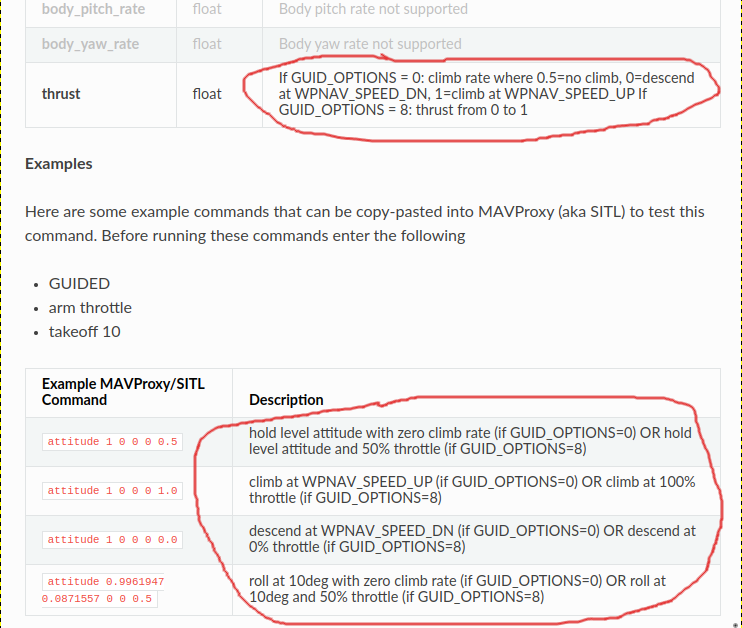
If the external system is capable of providing thrust then set GUID_OPTIONS = 8 and set the SET_ATTITUDE_TARGET message’s thrust field to a value between 0 and 1. This is good for situation where the external system can provide updates at a very high rate and has good built-in PID controllers.
If the external system wants to provide a vertical velocity instead then set GUID_OPTIONS = 0 and set the SET_ATTITUDE_TARGET message’s thrust field to a value between -1 and +1. The thrust field’s value will result in the vehicle flying down or up at a vertical speed between WPNAV_SPEED_DN and WPNAV_SPEED_UP.
As Randy pointed out we originally used SET_ATTITUDE_TARGET thrust as climb rate because this was pretty much the first message we ever implemented and this was something useful we could do. I would like to fix this and allow people to use the z axis of SET_POSITION_TARGET with SET_ATTITUDE_TARGET to do altitude control. This would be consistent with the current message specification and provide a lot of extra flexibility. This is work for the future.
As Randy said, the easiest thing is to use the vertical velocity version of SET_ATTITUDE_TARGET and let the autopilot control the altitude.
To directly answer your question. If you don’t want to use the vertical speed version of SET_ATTITUDE_TARGET then you will need to reproduce what we do for our controllers in the vertical axis. It will be difficult for you to get the same level of performance as Alt_Hold does because we have a fast acceleration controller at the base and also scale the thrust based on lean angle. You won’t be able to get the same update rate through mavlink. You don’t need ultra fast though so it is all doable, just a lot more work.
We added SYSID mode to support more complex controller design and things like model based tuning. So you are correct this could be used to potentially improve the performance over our current controllers. However this isn’t the approach to take if you want a fast solution.
Thank you Leonard and Randy for quick reply.
Yes, I’m aware about the behavior of GUID_OPTIONS = 0 plus WPNAV_SPEED_*
But this option is suitable for simple cases since WPNAV_SPEED_* is sort of fixed value and can’t be changed rapidly during the flight (correct me if I’m wrong).
I was considering SET_ATTITUDE_TARGET as a boundary or API which separates low level attitude control and “high level” commands like orientation and thrust which can be used by companion computer for dynamic flight.
Of course things are much more complicated. But this comment gives a little hint where to look at:
I understand that it won’t be possible to have same update rate as autopilot has. Since the thrust distributes forces in all directions, what about horizontal speed? So basically we need to establish relation between thrust level + vehicle attitude and velocity in x-y-z directions (easier to say than implement )
Also would be great to hear you thoughts how to correctly establish the relation between thrust level (0…1) and real force produced by the drone in order to use this as control input and get predictable vehicle movement.
Something here doesn’t sound right. You may have misunderstood what Randy said. You can choose any value of climb between WPNAV_SPEED_DN and WPNAV_SPEED_UP. So there should be no need to change this as you seem to suggest here:
As long as you don’t want to exceed WPNAV_SPEED_DN and WPNAV_SPEED_UP you shouldn’t need to change them.
It sounds like you are actually interested in using full manual control of throttle anyway. Personally I think this is the fun (but challenging) option. You need to budget a significant level of effort to get things to a point where you are happy with the performance though.
This is pretty easy for the first pass but then gets very difficult. At the base level you can assume a well setup and designed aircraft and that we have linearised the thrust curve properly. You can also assume that inflow velocities are small and not impacting thrust dramatically. Then you can use a simple geometry, gravity, drag model. This is basically what we do in the code and rely on the PID and sensible limits to deal with the corner cases.
It gets more difficult if you want to model inflow and non-axial flow. There are some models you can use to approximate these things but nothing that will give great results over the entire flight envelope. Then there is large sets of measured data and curve fitting. All these options are possible but a bit of a world of pain. Fun though
With this information in mind I will probably re-think how I can use it for my use case, since it moves a lot of responsibility to the autopilot.
But now the open question is: what coeficients should I trust? According to Randy’s answer I suppose 0 should be used if I don’t want to descend or climb, but according to example in docs it’s 0.5
Hold altitude is set at 0.5 for Guided Options = 0, which is equivalent to altitude hold. For systems that handle reverse thrust, 0 represents the altitude level for holding the thrust.
To ascend, set X > 0.5; to descend, set X < 0.5.
When Guided Options is set to 8, the system becomes significantly more responsive along the Z-axis. However, it becomes more challenging to fly since it operates similarly to ACRO.
One more follow up question.
In your talks you often mention “desired” and “achivable” states. With SET_ATTITUDE_TARGET it’s especially important not to request something that’s hard to achive or will make the vehicle unstable. Is there any practical suggestions how to stay on the safe side?
It depends on what you are doing. For example if you were doing acro control with both the quaternion and the angular rate commands everything will start to get out of shape if you command angular rates or changes in those rates that exceed the capability of the aircraft.
This could be as simple as asking for lean angles that mean the aircraft can’t maintain altitude but you are assuming you have enough thrust to not loose height.
To answer the question directly I would say start slow and work up. As you get more aggressive with your control you will start to find corners where things start getting ugly. If you start conservatively and work up you will already know that things were working well before. If you start too aggressive it can be very hard to work out why things aren’t working as you expect.
Got it, thank you. Assuming I’m controling the drone in the moderate conditions, meaning it’s not very close to it’s limits, would it be correct to infer it’s horizontal velocity based on it’s vertical velocity and lean angles? If it’s a valid assumption, then the opposite would be also valid, and I could transform my desired horizontal velocity into vertical velocity which is send to autopilot
Lean angle produces a force and acceleration in a given direction. You speed will continue to build until the drag increases to match the force. To estimate the drag you will need to account for both profile drag and momentum drag (drag due to the propeller thrust changing the direction of airflow).
From that relationship you could generate a curve of lean angle vs speed.
Your vertical velocity is not strongly coupled to your horizontal velocity vs lean angle.
So you can do what you are considering, you just need to get all the relationships together. A simple force vector in the z axis, mass and drag does work pretty well.
When I move forward during flight and then adjust the yaw angle, can I use the IMU to estimate the orientation of drag resulting from inertia? I’m not interested in velocity, my goal is to estimate the direction in 3D space relative to the body frame or NED frame in which I am currently flying.
Could you point the direction in which way to do it?
Yaw angle has no impact on your ability to measure drag assuming you have a normal multirotor with reasonably consistent drag coefficient around the horizontal axis.
I have been assuming you are using some sort of position feedback payload, something like slam or similar. The EKF needs some sort of position reference or at least velocity reference to calculate the bias of the IMU. Otherwise you need high quality IMU’s that don’t drift.
So I am not sure what you are trying to achieve now.