When controlling the Hexsoon Leds in lua(I downloaded from the examples). My RCOut: PWM:1-12 however my ProfiLED script used pins servo 13-14. this is causing " PreArm: SERVO14_FUNCTION=94 on disabled channel i think". I tried changing the “BRD_PWM_COUNT” but this param no longer exists. Can someone please help me overcome this pre-arm check…
Board pwm count is only in the older firmware, it has been changed to individual assignment via one of the servo_x parameters
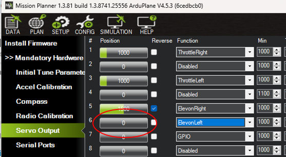
Yes i am aware of this thank you. So i set the SERVO13 func to “ProfiLEDClock” and SERVO14 to “script1”. When i do this the script works. But i get the pre-arm error saying “PreArm: SERVO14_FUNCTION=94 on disabled channel”. I dont understand why im getting that fail-safe trigger preventing me from arming… ![]()
I dont know either, you may be able to remove it from the arming mask if you cant work it out, but someone will know
This is a bug that has now been fixed, you can patch the script to set (not save) that parameter back to -1 after it has setup the LEDs. This fixes the arming check.
Thanks so i added this line just before the “update_LEDs()” definition and it worked.
– Add the following line here:
param:set(‘SERVO14_FUNCTION’, -1)"
However not my motors don’t spin. and the ESC protocol is set to oneshot125. Im guessing the script is conflicting with the pwm clock?
Could you point me at the bug fix, so that I can retro-fit it to 4.5.3? I’m on a corner where the master (4.6.1) won’t compile but 4.5.3 will. Cheers.
Hi Steve,
This is the fix
Ah, many thanks. It looks like my problem is deeper than that - the Flywoo F745 AIO erroneously tags one of the PWM channels (connected to a control surface servo) as disabled. Any ideas what might causing that?
Can you post your params file? PWM6 is its own timer group, there shouldn’t be any problems with it.
MicroM1-14-7-2024.param (23.2 KB)
Hi Peter. Sorry about the delay - here it is. I was playing around with workarounds and found that setting the pin to GPIO, rebooting the board, and then setting the pin back to PWM got it working. I think that this pretty much what your scritped fix does?
To add a bit of complication, I have fiddled with the hwdef.dat file to remap UART pins to PWMs, which otherwise aren’t supported on the Flywoo F745. Here’s the tweak:
USART1
PA10 USART1_RX USART1 NODMA # PA10 stolen for PWM
PA9 USART1_TX USART1 # PA9 stolen for PWM
USART2
PD5 USART2_TX USART2
PD6 USART2_RX USART2 NODMA
USART3
PB10 USART3_TX USART3
PB11 USART3_RX USART3
UART4
PC10 UART4_TX UART4 # PA0 stolen for PWM
PA1 UART4_RX UART4 NODMA
UART5
PC12 UART5_TX UART5 NODMA
PD2 UART5_RX UART5 NODMA
USART6
PC6 USART6_TX USART6
PC7 USART6_RX USART6 NODMA
UART7
PE7 UART7_RX UART7 NODMA
PE8 UART7_TX UART7 NODMA
Motors
PB0 TIM3_CH3 TIM3 PWM(1) GPIO(50) BIDIR # Motor 1
PB1 TIM3_CH4 TIM3 PWM(2) GPIO(51) # Motor 2
PE9 TIM1_CH1 TIM1 PWM(3) GPIO(52) # Motor 3
PE11 TIM1_CH2 TIM1 PWM(4) GPIO(53) BIDIR # Motor 4
#PC9 TIM8_CH4 TIM8 PWM(5) GPIO(54) # Motor 5
#PA3 TIM5_CH4 TIM5 PWM(6) GPIO(55) # Motor 6
PB4 TIM3_CH1 TIM3 PWM(7) GPIO(56) # Motor 7
PB5 TIM3_CH2 TIM3 PWM(8) GPIO(57) # Motor 8
PA0 TIM5_CH1 TIM5 PWM(5) GPIO(54) # PWM 5 instead of UART4_TX
PA9 TIM1_CH2 TIM1 PWM(6) GPIO(55) # PWM 6 instead of UART1_TX