I’ve got a small (~2 kg) transverse tandem heli, built from the main motors/rotors of a pair of Sab Goblin Fireballs (2-blade head). Each rotor is driven directly from a separate motor - no belts or torque tubes. Generally speaking everything is working well but since both motors are controlled from the same motor output channel, there’s a small difference between the left and right rotor speeds (even with ESC calibration). The rotors aren’t overlapping/meshed so there’s no issue with blade collisions, but this does introduce a noticeable beat frequency, typically around 0.8 - 1 Hz.
The attitude/velocity/position control and EKF all don’t seem to mind, and the beat frequency doesn’t seem to be causing any resonance or feedback instabilities - probably luck more than anything since I haven’t run the SYSID and I don’t know exactly where those pitch/roll/lead-lag modes are lurking.
I feel like writing a second motor object into the AP_MotorsHeli_Dual class - sort of like how a tail_rotor object is created in AP_MotorsHeli_Single. It seems doable, but is this better left as “it ain’t broke so don’t fix it” or could there be some actual benefit to being able to fine-tune that beat frequency by having independent RSC outputs to each motor?
Even if I can get the RPM equalized between the two rotors, could I be making the vibration worse since I won’t have control over the phase/azimuth of each rotorhead? (they could be in sync, could be 90 degrees off, could be any angle …)
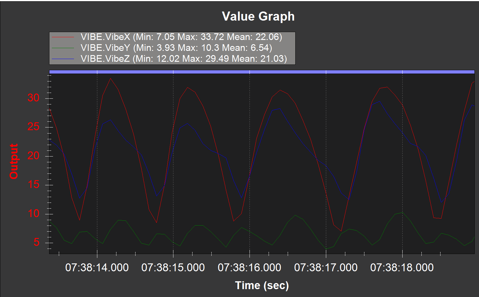
This is a very low frequency but I’m assuming that your rotor speed is on the order of 1200-1500 RPM. Even if your rotor speed was lower, lets say around 1000 RPM, this is still a very low frequency. What you are showing in the graph is the Vibe signals and those are showing RMS (or something like that) of each accelerometer. This is not a raw IMU signal. I think you would see more coupling from the rotors show up in the pitch gyro signal (this is a side by side configuration like a V-22 not like an H-47, correct?)
So why don’t you use ESCs that govern rotor speed and just set them to the same rotor speed. What RSC mode are you using?
As long as the rotors are dynamically balanced well, I think having them in exact phase with each other is NOT crucial. I think the big concern would be lead-lag modes between the two rotors coupling but there is not much you can do to control that other than designing the structure to be stiff enough to absorb coupling between the rotors and the fusalage (don’t let them get into resonance with the fuselage).
It’s a pair of 280 size rotors, so it’s up around 3400 RPM. But that would be further to your point that this is a VERY low frequency compared to the rest of the main rotor vibration.
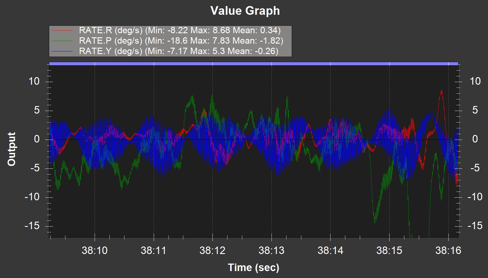
It’s a side-by-side tandem, yes. Strangely it shows up around the gyro Z axis the most. I was doing some IMU batch sampling so I didn’t have the raw IMU logging (Measuring Vibration with IMU Batch Sampler — Copter documentation) but it shows up nicely in the RATE.Y values.
TBH I didn’t think those existed in small heli ESCs. I’ve been using what I had The SAB kit comes with a SAB branded hobbywing ESC and the RPM can’t directly be set in the ESC - rather H_RSC_MODE is set to 2 and the RSC setpoint was adjusted using an optical tach to read the RPM. Both ESCs were calibrated to the same throttle range and the rotor speed came out within about 45-60 RPM of each other (which gives the beat frequency of ~ 0.8 - 1 Hz)
I’ve seen your V22 video with the engine shaking about the pitch axis. Is this what you’re referring to?
Wow I didn’t know the aircraft was that small. I’m not sure if the ESCs for those size heli’s have built in governors. I think what you are doing will work. There might be some difference in thrust between the two sides but 40-60 RPM is less than 2% difference. So I think the controller should be able to compensate for that.
Yes, that is what I was referring to.
Yes, the IMU batch sampling is a nice feature. Did you know that you can use that data to perform an FFT and see the different frequencies in the data?
Yeah the small heli ESCs are pretty full featured. Built-in store governor and all, so generally speaking the headspeed stays pretty solid for each rotor and keeps the headspeed from sagging as the battery depletes. It’s getting them to be the same speed that can be a little more interesting but from what I gather this isn’t necessarily a problem.
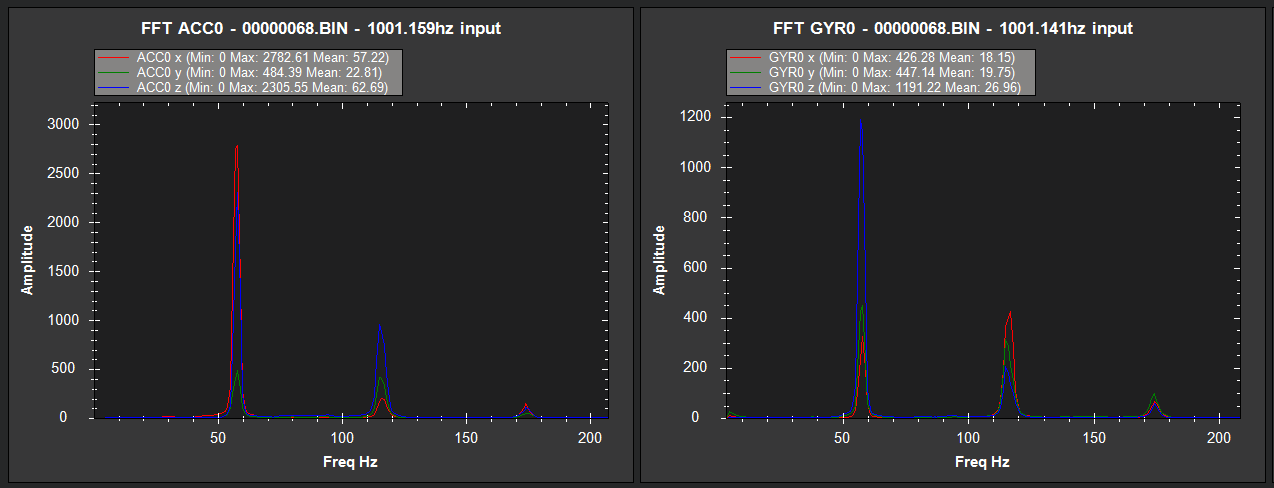
I’ve got that data in front of me as well and was going to bring that up in a separate thread. Might as well ask now … I can very clearly see the 1/rev, 2/rev, and 3/rev vibrations but I was a bit blown away by the the amplitudes of ACCX, ACCZ, and GYROZ. To be fair I have no idea what the units for amplitude are, but looking at other posts around here there are magnitudes of tens-to-hundreds of units and mine show up in the thousands.
This is the pre-filtered FFT. I haven’t played with notch filtering or anything like that yet, just a 10Hz IMU filter on the accel/gyro.
@Murdoch yes the FFT analysis in Mission Planner of the IMU batch logging data is not the best. First it includes all of the batch logged data which includes data while the aircraft is on the ground and second, it doesn’t normalize the FFT amplitude. it is helpful to see what vibrations the aircraft control system is experiencing, especially after you apply the harmonic notch filter. However, to do more with it than that, you’ll need to develop your own frequency analysis tools that use the IMU batch logging data.