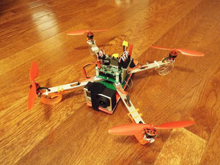
A few years ago I purchased a mini quad copter for myself as a christmas gift. I learned to fly this mini quad copter and that inspired me enough to build a DIY quad copter. I decided to learn more about these micro electronic so this is what I created. For a more stable frame I used four aluminum arms from an old computer hard drive storage array. (dimensions - 13in x .5in x or 330.2mm x 12.7mm) For the mounting base I harvested an old 10/100 baseT network card and removed all the ic chips, resistors, and soldered parts that were on the board. I cut it in half and super glued the arms to the board. As shown in the image above.
Here is my parts list: note - thank you for the comment @supernoodle2014
- I purchased everything from http://www.kynix.com/
(4) 1811 Outrunner 2900kv brushless motors (all 4 - $47 USD)
(4) Plush 6A /.8bec/6g Speed Controllers (all 4 - $44 USD)
(4) 5030 Propellers (Red) - 3xCW and 3xCCWKK2.0
(1) Multi-rotor LCD Flight Control Board - KK2 - $20 USD
(1)9x8cv2 Receiver
(1) Multi-Rotor Power Distribution Board
(1)1000mAh 2S 30C Lipo Battery Pack - $6 each
During the initial build I tried a few different configurations, but found the best setup below. The electronic speed controllers and network card are attached to the arms with 3M double sided tape from Lowe’s. I used a combination of super glue and 3M tape to connect the multi-rotor distribution board. I brought the signal wires, red and black power wires up through the middle of the board; then cut them to length and soldered the red/black leads to the distribution board.
Step 1: Mounting boards, speed controllers, and electronics
https://cdn.instructables.com/FI0/C9JM/IM28VESR/FI0C9JMIM28VESR.MEDIUM.jpg
I ended up mounting the motors upward & turning the distribution board in more of an X configuration. I continued the build and glued (ca) four capacitors from a computer motherboard to the network card. Then I glued the distribution board to the top of the capacitors along with a blank circuit board onto four more capacitors. I applied a piece of double sided tape to the circuit board to hold down the foam protector that the KK2 (flight controller) board was shipped in and added a plastic electrical tape container to the bottom for the battery. I used five 1" servo leads and connected them from the KK2 to a Turnigy 9x8cv2 receiver board. Used two more capacitors and glued them to the foam and receiver board with enough clearance to still access the KK2 programming buttons. Finished up by connecting the signal leads from the esc’s to the KK2 starting with 1,2,3,4. Please note that 1,3 are cw and 2,4 are ccw.
Step 2: After my maiden flight
https://cdn.instructables.com/FOX/QYM6/IM28VEGB/FOXQYM6IM28VEGB.SMALL.jpg
After the maiden flight and while close to the ground the copter did an erratic flip after about 3-4 minutes of flight time. I was pretty confused as to what happened so I took the copter inside and started thinking weight and possibly the kk2 board settings. I ended up taking the battery holder off and attaching the lipo to the bottom with velco. I ran a few more tests and still only 3-4 min of flight time on a fully charged battery. Thinking about weight, I started to google the flip issue and read on the forums that some folks were isolating a failing ESC. Before replacing the motor I decided to test this setup again. Reproduced the erratic flip and immediately touched all of the ESC’s and motors. I felt motor #1 and it was well above the normal temp. So I decided to re-soldered the #1 motor and ESC’s connections and “BAM” I was now getting 6-7 minutes of flight time without any erratic flips. Now having a good battery, ESC’s, and motors I was able to then work on the kk2 board settings.
Step 3: More design and modifications
I made some mods to the design to try and make the quad lighter - removed the foam and the battery holder for starters. Took off the capacitors and used standard nylon stand off’s.
I added some cheap plastic landing gear that I picked up from Party City - nifty idea - these are just plastic table cloth clips. They provide some cushion and are cheap and easy to replace.
First I took off the kk2 board and the foam. Then plugged in the battery alarm onto the board. After this I soldered a female jst plug onto the bottom of the kk2. Then connected to a male jst that was then soldered to the power board. I then removed the RX module out of its shell and sealed it with clear shrink wrap and hot glued the end. All I needed to do now was to mount the rx to the kk2 board with double sided stick tape.
Step 4: Flight Video
please click here.
Please note that I am still learning how to fly and still need help turning around and flying back. Any feedback would greatly be appreciated!
I hope this build helps some of you folks that love to tinker as much as I do!!
Step 5: Adding a GoPro 3
I decided to push this little quad and try my luck mounting a GoPro to it. My goal was to get some flight video. This is what I can up with - cheap piece of dollar tree foam, wire ties, and some velcro. I did not know what to expect, but the video came out pretty good; no jello or crazy vibration.
