The SITL binary ./build/sitl/bin/ardurover does not seem to recognise the -f flag. It accepts --model sailboat but still publishes rc 3 rather than rc 4. I’ll dig into it when I have a moment and see if I can figure out what’s going on.
Hi Peter, quick question: I’m setting up a VM to run Windows10 and WSL to try and replicate the issue you are seeing with the docker image, do you run WSL or WSL2?
WSL2, It seemed to be a more fundamental docker issue, but I really have no idea.
Hi Peter, I’ve managed to get the simulation docker image up and running on a Windows 10 VM. It’s woefully slow for reasons I don’t yet understand (it runs at 1% real time whereas the same image running on an Ubuntu VM with the same spec: 4 processors, 8GB RAM runs at 95% real time). Anyway, if you’d like to try and get it running I’ve documented my setup steps which I’m happy to share. There was a bit of fiddling about to get OpenGL running on WSL2 - and that may be the reason for the performance issue, but I really can’t tell at this point.
1 Like
Peter, the reason the simulation runs slowly on WSL is because at present there is no acceleration for applications using OpenGL 1.4 or greater (which applies in this case). This question on superuser has a detailed explanation: How to troubleshoot OpenGL on Ubuntu under Windows 10 (WSL) (see the section titled ‘Explanation of under the hood’). I tested by running both the docker image and the entire project built from source in WSL.
I was able to get some improvement in the real time factor (up to 40-50%) by allocating additional memory and processors to WSL using a %USERPROFILE%.wslconfig file:
[wsl2]
memory=6GB
processors=4
however the frame rate remains very low (2-3 FPS) because the CPUs allocated to render the ocean scene are having to work very hard. However the simulation does run and you get the physics just not the visual experience.
The good news is that Microsoft are planning to bring hardware acceleration to WSL: (see this article DirectX and WSL). It’s available for ML applications in a beta already but GUI use is still to come later this year apparently. In the meanwhile the options are to use a virtual machine to run Ubuntu from a Windows host, which will have hardware acceleration, or for me to provide a version of the simulation with a lower OpenGL requirement (not really feasible sorry!).
1 Like
Hi Peter, I’m trying to inspect the data coming from SITL using DroneKit-Python and am wondering how to get the SAIL attributes such as SAIL.WndSpdTru etc.
Here’s the setup:
-
SITL running using
sim_vehicle.py -v Rover -f sailboat --console --map
This is routing output to udp:127.0.0.1:14550 and 127.0.0.1:14551 -
A DroneKit-Python script connecting to udp:127.0.0.1:14550
-
QCS connecting to udp:127.0.0.1:14551
I can see a lot of the MAVLink messages in QCS using the MAVLink inspector, but not the SAIL ones.
Also, I can graph some of the outputs in MAVProxy using the graph module, but if I try: AUTO> graph SAIL.WndSpdTru for example, no data is displayed.
I’m missing something in the configuration / setup but am not sure where to start looking, any suggestions?
The SAIL stuff is in the onboard log, but not sent back over MAVLink.
You can get the true wind speed and direction in the wind message, but none of the other sailboat specific stuff.
You can graph these in MAVProxy with graph WIND.speed and graph WIND.direction, in mission planner you can plot on the tuning graph / the HUD / the quick gauges with wind_vel and wind_dir. No doubt there is also a way in QGC, but I’m not very familiar with it.
A nice MAVLink message to send back lots of useful sailing stuff is on the todo list…
1 Like
Thanks Peter - that all makes sense. I’m putting together a python script to replicate your polar calculation for the Gazebo sim as a way of getting to grips with some of the ArduPilot tools and interfaces. Hopefully I’ll be able to help out with some of the sailing dev work as I get more familiar with the code.
1 Like
I did have a vague idea of running a polar calculator in lua on the flight controller. You could save to a csv file and grab it via MAVFTP. That way it would work for real vehicles too…
My thought was to do some sort of speed histogram for true wind angle in 5 deg sections. Not sure the best way to cope with changes in wind speed tho. I guess have a set of histograms per wind speed, again in some sort of section.
Again, its on the list…
They have a lift/drag polar calculator in the soaring code now I think, maybe that would be a good place to start
1 Like
Sounds good. At one point I did attempt to generate polars from sensor data gathered on a full size boat - it was very noisy. I was using water speed from the log (noisy and subject to bias) and magnetic heading data (noisy) and estimated true wind speed and heading from sensor on top of a rotating mast (more noise!). I’d be interested to see how the soaring code solves it.
1 Like
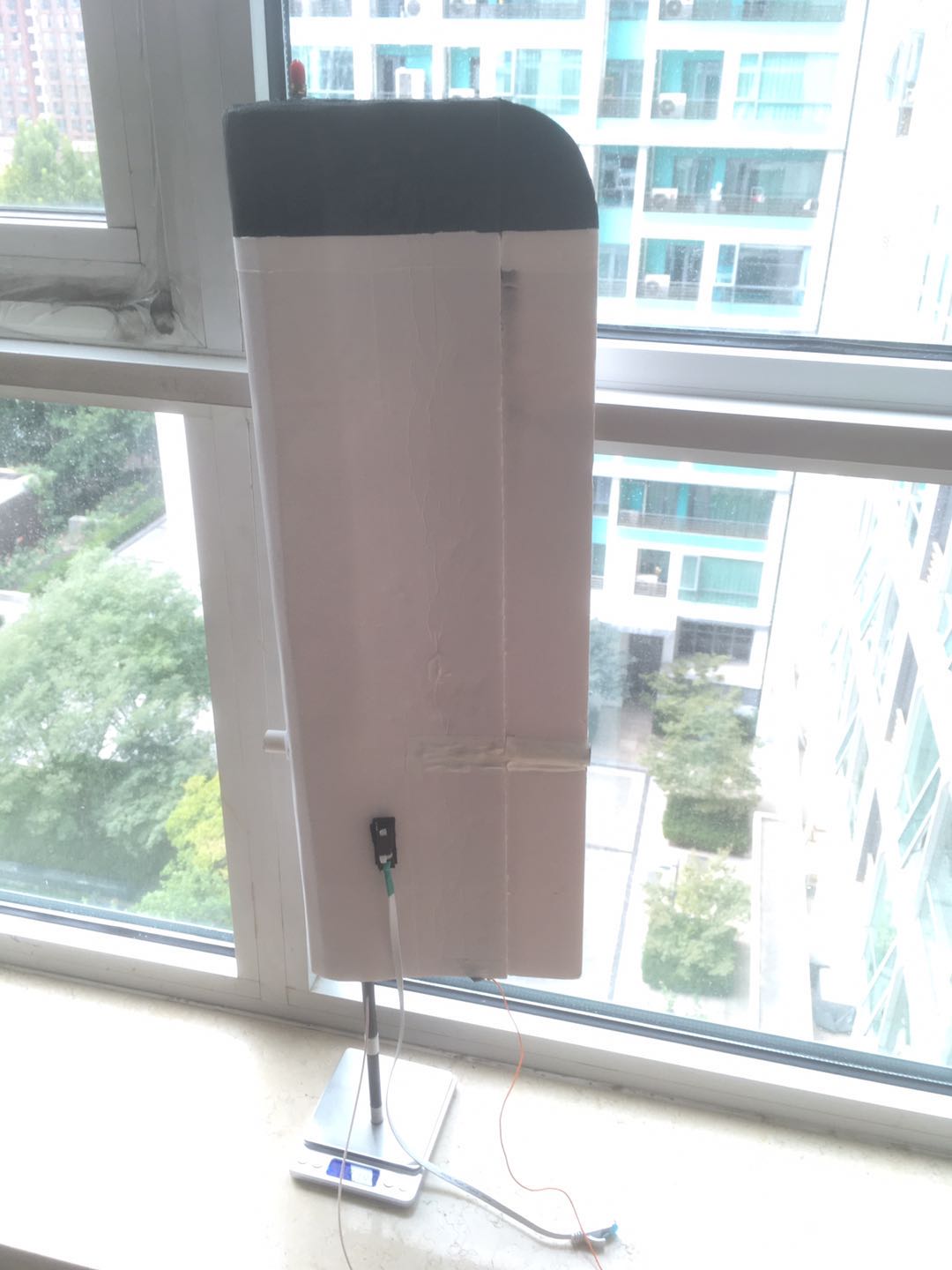
@karla I’m putting a boat together and have been reading through your thread on the wing sail for the laser. Could you tell me what the weight of the foam board wing was? (just the wing - not all the vane and counterbalance support structures). My boat is a bit of an experiment with 3d printing, and I’m wondering whether a printed monocoque wingsail is feasible given weight constraints. A rough estimate has each 200mm section of a 360mm chord wing with 0.5mm skin thickness weigh in at about 120g and I was interested in a comparison.
Wow,
Is this what you up to?

I think your weight is very low compared to mine.
The larger wing is ~515 gram and the smaller is ~315 gram.

1 Like
Hi Karl,
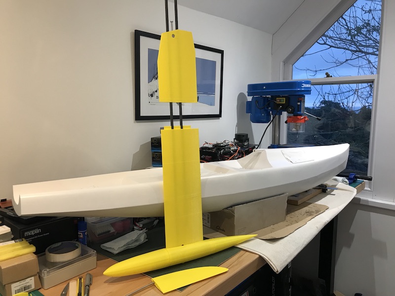
Thanks for the measurements. I’m not attempting anything so adventurous I’m afraid!, although that would be some boat. My boat is a variant of a 10R Sabre. I’ve added more beam / volume for carrying electronics etc. so it wouldn’t measure as a 10R but I’m hoping it will be good as an autonomous boat.
The hull comprises eight approx 200mm x 1mm sections seamed together with the main reenforcing coming from a keel box and cross struts. The keel sections have a 1mm skin and 3d honeycomb infill with slots for two square section carbon tubes.
The bulb is hollow and will be filled with 3.8kg lead shot and epoxy.
A conversation with Peter started me thinking about whether it would be feasible to print a hard sail as well. I know that people have made RC planes with printed wings, so it seems possible. I’m constrained by my printers volume - so have sketched out a 1800mm x 360mm (area = 0.65 m^2) wing using the same NACA0018 section you used to estimate weights and it would come in at 1.1 kg - which is a bit more than your wing but might still be ok. The maribot wing is 25 kg for a surface area of 2.7 m^2.
It seems worth trying and I’ll post progress as the boat is fitted out. This thread has been super useful as a source of ideas and information.
1 Like
Nice 
The area of my wing sails are 0.241 respectively 0.133 mˆ2.
This should be ˜ 0.5 mˆ2 sail area per kg weight.
So I think you get much more sail per kg than I do, like 1.1 mˆ2 ?
From that perspective you should be good.
I have noticed that, given the same sail area, the traditional (triangle shape) sail behave different from a rectangular wing sail. The Laser can take considerably stronger winds with a traditional sail than with the wing. I think this is due to relatively more mass and sail area higher above deck. The Laser will not sail well over 5 m/s winds with Wing A.
So I am just thinking, consider try reduce weight at top and maybe (like the Sailbot example) change the shape so smaller area at top of mast?
Looking forward to your development!
1 Like
That’s useful info about the need to use a smaller wing compared to a conventional rig. I’ve drafted a 360 x 1400 wing with the same aspect as the wing used by the Maribot WingSail_v8.stl (277.9 KB). It is about half the area of a 10R A rig. Next step is to figure out how to attach the trim vane. I plan to follow the design used by a later variant of the Maribot wing which used a vane fixed to a rotating rod supported by a tube angled at 70 deg with the servo in the main wing body.
1 Like
Yes, I had my eyes on that one too, it should have some benefits over the simple straight 90 degree ones. I found it too complex and heavy to implement on the Laser though.
I think the more recent Saildrone.com versions has also gone that way with the control surface higher up and at a higher angle from mast. I went the other way and moved the control surface down closer to deck.
Anyway its a good idea to already at design stage think over what useful components can be used as counter weights.
The reason to have the control surface as high as possible is that it is generating a force in the opposite direction to the force of the main sail. You have to have a constant force independent of the height, but putting it as high as possible cancels out more righting moment from the main wing. So you end up with designs such as this.
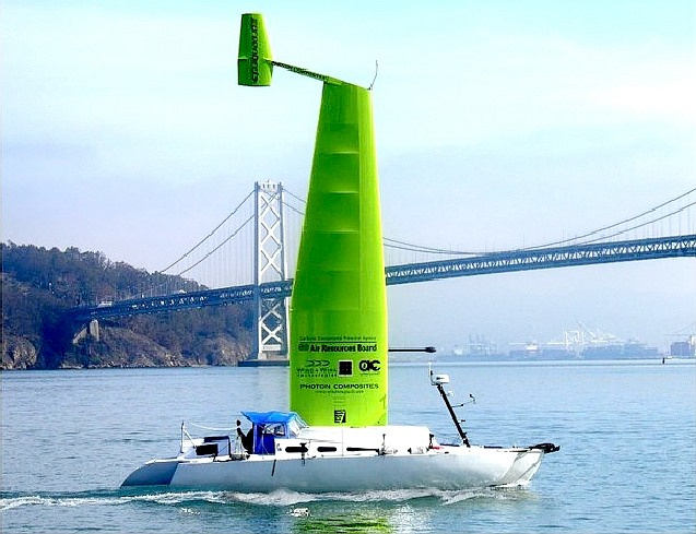
This is actually from the Saildrone guys, quite a interesting article about there origins.
1 Like
Hello, I am not an expert at all about rigid sails, but I wonder how do you cope with bad weather and high wind, i.e. those situations where on “normal” sailboats you reduce the sail surface or close the sails at all
I guess that for a robotic system, maybe unattended for sevaral days/weeks in blue waters, the topic is relevant…
The reason you have to reduce sail size with a soft sail is that you can’t let it out too far.
If you a spilling too much wind the sail will stop being a sail and just flog, the transition to flogging also has a huge increase in drag, this will stop you dead. If you have ever been sailing in strong winds you will know its much easier to keep sailing slowly than to let the sail out completely (admittedly this is also because you can only steer if you moving), once the sail starts flogging it shakes the whole boat.
Hard wings do not flog in this way, and have a very low drag coefficient when feathered into the wind.
There are also piratical considerations, much easier to make a durable wing sail than soft one. You can put antennas and such inside it (so long as its not metal or carbon). They can also be made to float so you cant invert.
Soft sails do have the advantage that as you reef them down you also lower the center of pressure reducing the heeling moment. ‘Fancy’ wing sails have twist control to achieve the same thing, but this is not worth the complexity unless your racing.
Thanks !
So if there us too much the wing sail is left free to align with the wind, reducing the force to pure drag, right ?
The mechanism to allow free frictionless rotation when needed but fine control of the angle of attack when sailing I guess is quite sofisticated, isn’t it ?