Home
Blog
Stores
Docs
Copter
Plane
Rover
Sub
ArduPilot Discourse
Sailboat Support
ArduRover
ArduBoat
karla
(Karl Alberts)
June 9, 2019, 5:39am
321
Hi all,
I am still long way from testing how it will work.
But at least some progress
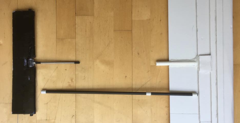
IMG6.jpg
937×481 27.3 KB
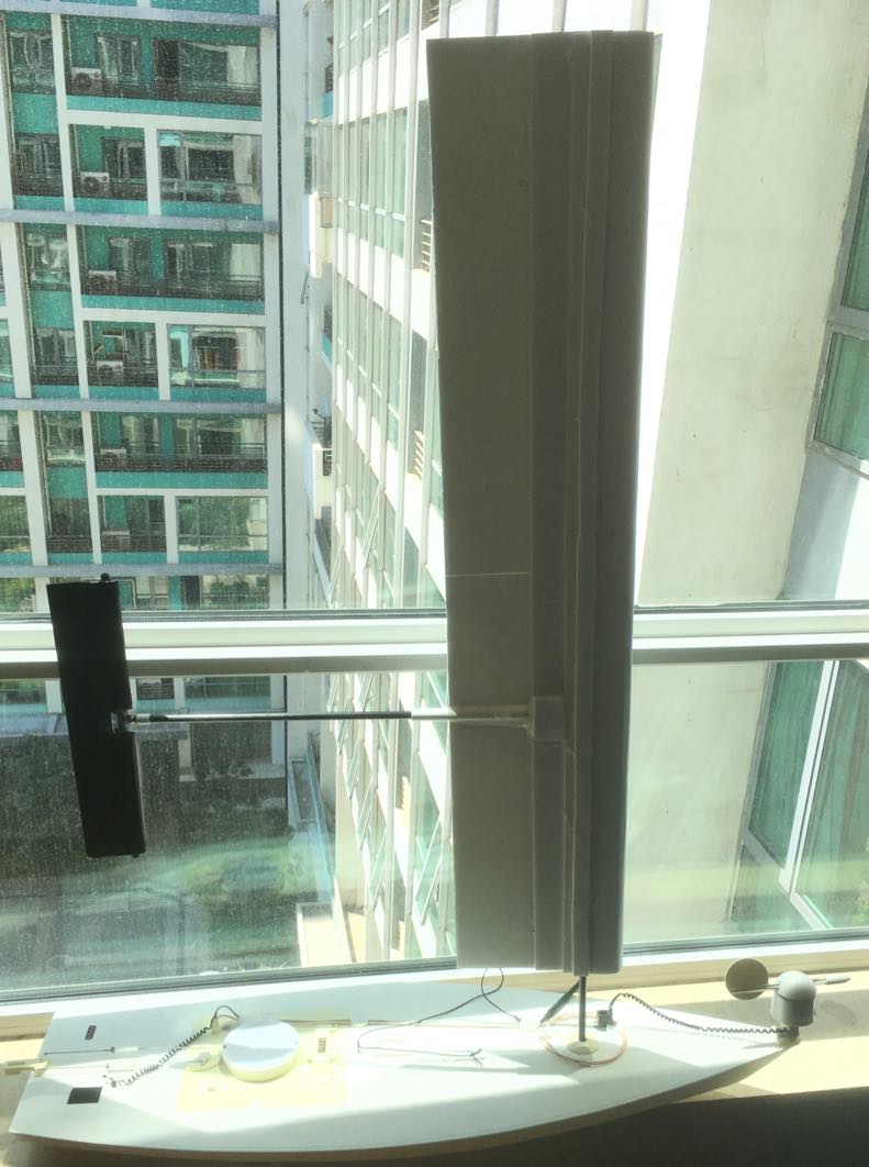
IMG7.jpg
791×1062 92.7 KB
1 Like
show post in topic