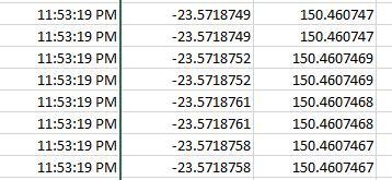
Hello everyone!
A friend asked me about this topic and pointed me to this thread, so I came for an update and some further questions. Plus, hunting error sources is fun.
I’ll try to make this a “tutorial” post, present the whole image I have on the topic and ask some questions on top of that.
Goals:
Obtain accurate positioning data with the intention of:
- stamping photos, for use in mapping applications
- position feedback for UAV position control
Note: The discussion is based on the assumption that very accurate RTK GPS systems are available to the UAS.
Information Path
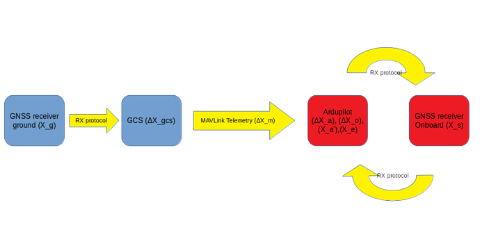
- A GNSS receiver on the ground station records position solutions: X_g
-
X_g is converted to RTCM correction data [2] and sent to a GCS, which records it as X_gcs [3]
- The GCS sends the solution to the UAV through the
GPS_RTCM_DATA MAVLink message [4], containing X_m. The corrections are sent as a binary blob, possibly fragmented into up to 4 messages and sent across multiple messages.
- Ardupilot captures the MAVLink message and unpacks the RTCM packets into an ‘rtcm_buffer’ struct [5]. It stores the correction data struct ΔX_a until it is complete.
- Ardupilot sends ΔX_a to the onboard GNSS receiver [6], repackaging it as ΔX_o (the original form), according to the receiver driver [7].
- The onboard GNSS receiver calculates the correction, creating a more accurate solution X_s
-
X_s is sent from the onboard receiver to Ardupilot, which stores it as X_a’
- Ardupilot uses X_a’ in its EKF [8], producing a final position solution X_e [9]
The following image visualizes this information path:
Quantity Representation and Precision
The following table summarizes the representation of each quantity and the precision it can achieve.
All quantities are in degrees when expressed in floats and degrees * 1e7 when expressed in integers.
| Quantity |
Representation |
Representation Precision |
Actual Propagated Precision |
| X_g |
(Based on driver) |
(maximum) |
(maximum) |
| X_gcs |
(RTCM) |
(maximum) |
(maximum) |
| X_m |
MAVLink GPS_RTCM_DATA
|
(maximum) |
(maximum) |
| ΔX_a |
uint8_t rtcm_buffer::buffer |
(maximum) |
(maximum) |
| ΔX_o |
(Based on driver) |
(maximum) |
(maximum) |
| X_s |
(Based on driver) |
(maximum) |
(maximum) |
| X_a’ |
int32 |
full (integer) |
(degrees, 7 digits at best) |
| X_e |
float32 |
7.2 digits [1] |
(meters, decimeter-level) |
Specifics on EKF implementation
For this section, we shall examine EKF3, which is the latest EKF revision.
Every Kalman filter has
- a measurement update step, where sensor data is made available and read
- a model update step, where the internal model is propagated and
- an output step, where the filtered data is made available
In this case, EKF3 reads from the GPS driver
const struct Location &gpsloc = gps.location();
where the GPS location is made available in WGS84 coordinates:
struct PACKED Location {
    union {
        Location_Option_Flags flags;                    ///< options bitmask (1<<0 = relative altitude)
        uint8_t options;                                /// allows writing all flags to eeprom as one byte
    };
    // by making alt 24 bit we can make p1 in a command 16 bit,
    // allowing an accurate angle in centi-degrees. This keeps the
    // storage cost per mission item at 15 bytes, and allows mission
    // altitudes of up to +/- 83km
    int32_t alt:24;                                     ///< param 2 - Altitude in centimeters (meters * 100) see LOCATION_ALT_MAX_M
    int32_t lat;                                        ///< param 3 - Latitude * 10**7
    int32_t lng;                                        ///< param 4 - Longitude * 10**7
};
The current coordinates are subtracted from the EKF origin to obtain the current XY offset:
gpsDataNew.pos = location_diff(EKF_origin, gpsloc);
gpsDataNew.hgt = (float)((double)0.01 * (double)gpsloc.alt - ekfGpsRefHgt);
which is a Float32 variable:
struct gps_elements {
    Vector2f    pos;            // horizontal North East position of the GPS antenna in local NED earth frame (m)
    float       hgt;            // height of the GPS antenna in local NED earth frame (m)
    Vector3f    vel;            // velocity of the GPS antenna in local NED earth frame (m/sec)
    uint32_t    time_ms;        // measurement timestamp (msec)
    uint8_t     sensor_idx;     // unique integer identifying the GPS sensor
};
These are used during the model update to propagate the vehicle state. This state is declared as:
struct state_elements {
    Quaternion  quat;           // quaternion defining rotation from local NED earth frame to body frame
    Vector3f    velocity;       // velocity of IMU in local NED earth frame (m/sec)
    Vector3f    position;       // position of IMU in local NED earth frame (m)
    Vector3f    gyro_bias;      // body frame delta angle IMU bias vector (rad)
    Vector3f    accel_bias;     // body frame delta velocity IMU bias vector (m/sec)
    Vector3f    earth_magfield; // earth frame magnetic field vector (Gauss)
    Vector3f    body_magfield;  // body frame magnetic field vector (Gauss)
    Vector2f    wind_vel;       // horizontal North East wind velocity vector in local NED earth frame (m/sec)
};
In turn, this state is manipulated to produce the filter output:
posNE.x = outputDataNew.position.x + posOffsetNED.x;
posNE.y = outputDataNew.position.y + posOffsetNED.y;
declared as:
struct output_elements {
    Quaternion  quat;           // quaternion defining rotation from local NED earth frame to body frame
    Vector3f    velocity;       // velocity of body frame origin in local NED earth frame (m/sec)
    Vector3f    position;       // position of body frame origin in local NED earth frame (m)
};
Remarks
- EKF reads the GPS location in WGS84 coordinates which is already constrained in accuracy by its int32 representation at 11cm, truncating potential RTK precision. I don’t know if the otherwise superior position accuracy is correctly downgraded to reflect this truncation.
- The position measurement is stored as a relative coordinate in meters (float32) , converting from WGS84 coordinates to the NED Cartesian frame.
- The filtered position is returned in the NED frame in meters (float32).
Assumptions
- Correction data is transmitted through MAVLInk and the telemetry channel, not via a dedicated RF channel.
Conclusions
- The autopilot internal location representation is a bottleneck for the RTK solution precision, limiting it to 7 digits (about 11mm)
- It looks like the precision could me immediately improved by creating a more accurate GPS driver. The EKF is otherwise ready to accept the improved precision.
Further Questions
Is everything clear? Do you need better wording someplace?
Footnotes
[1] See https://www.h-schmidt.net/FloatConverter/IEEE754.html for actual error calculations.
[2] https://gssc.esa.int/navipedia/index.php/DGNSS_Standards
[3] https://github.com/ArduPilot/MAVProxy/blob/ec5cd22e22469d1107c0259bb71508fb99293e14/MAVProxy/modules/mavproxy_DGPS.py#L58
[4] https://mavlink.io/en/messages/common.html#GPS_RTCM_DATA
[5] https://github.com/ArduPilot/ardupilot/blob/90216f7cb6c5fd20cc5020b935a7985b1a549949/libraries/AP_GPS/AP_GPS.h#L505
[6] https://github.com/ArduPilot/ardupilot/blob/922d593f3d28cdd0959178ec2ae3cc41ce040ad0/libraries/AP_GPS/AP_GPS.cpp#L865
[7] https://github.com/ArduPilot/ardupilot/blob/1b6ec1d5ad33567e0bc62a2a1f6a5bb2b68fe31b/libraries/AP_GPS/GPS_Backend.cpp
[8] https://github.com/ArduPilot/ardupilot/blob/1b6ec1d5ad33567e0bc62a2a1f6a5bb2b68fe31b/libraries/AP_NavEKF3/AP_NavEKF3_Measurements.cpp#L565
[9] https://github.com/ArduPilot/ardupilot/blob/1b6ec1d5ad33567e0bc62a2a1f6a5bb2b68fe31b/libraries/AP_NavEKF3/AP_NavEKF3_Outputs.cpp#L239
Edits
- 2018/11/23: Incorporated RTCM data into the information flow.
- 2018/11/25: Updated information flow image, ArduPilot RTCM handling
- 2019/01/08: Traced the EKF3 internals

