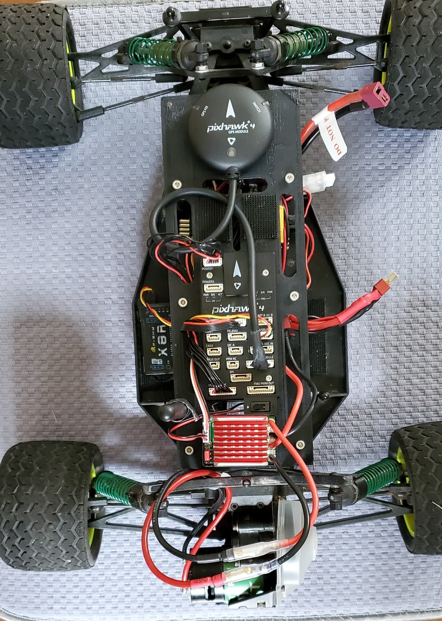
Having successfully built a quad with a Pixhawk 4 I figured a Rover build would be trivial but it turned out to be a challenge to my intuition. I"m sure there are other better ways but I got to thinking some notes might save others a bit of aggravation…
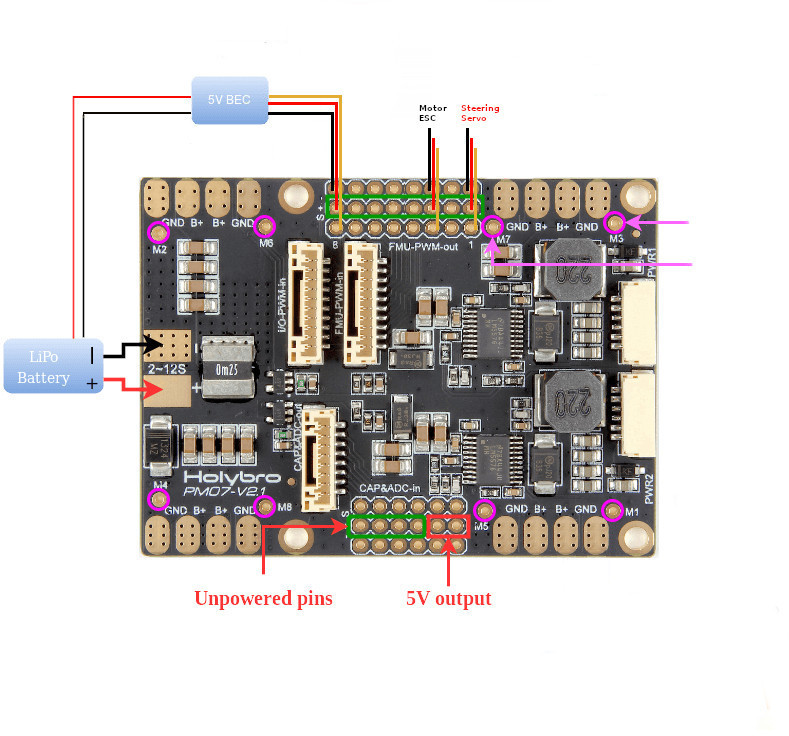
Connect 2S (7.4V) Lipo Battery to PDB, BEC and Motor ESC.
Use FMU pins as a BEC Bus to distribute 5V to the Steering Servo and the Motor ESC.
“Do not” connect the FMU wire harness between the PDB and the Pixhawk 4.
Connect Power1 (PDB) to Power 1 (Pixhawk 4).
Connect I/O PWM In (PDB) to I/O PWM Out (Pixhawk 4).
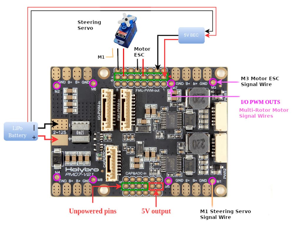
Solder Pin Headers to M1 and M3 on PDB for M1 Steering Servo Signal wire and M3 Motor ESC
Signal wire.
Mission Planner CONFIG Tab, Full Parameter List, Mods if necessary:
BRD_SAFETYOPTION = 0 (to disable safety switch)
ARMING_CHECK = 1046014 (All except 2048: Hardware safety switch); Click in the value box to choose options to turn on or off)
RTL_SPEED = 2 (m/s); (0 = Default)
The following CONFIG value fixed Rover spins in AUTO mode issue:
SERVO1_REVERSED = 1 (Reversed); (0= Default which is Normal
Added an Arm/Disarm switch to channel 7 on the transmitter:
RC7_OPTION = 153 (ArmDisarm); (0 = Default which is do nothing)