Just on another aspect of the moving baseline heading setup, I have previously struggled to get better than 5Hz output from both the base and rover. Without using corrections on the base, I can get a nice stable heading output - but even at just 5Hz, once I start sending corrections to the base and it computes an RTK solution, I still get relatively frequent heading drop outs on the rover. The best I have been able to achieve is 8Hz solutions on both the base and rover, but this was achieved by excluding the Glonass and Galileo constellations. I believe that the timing of the corrections between base and rover is critical and when the base is bogged down computing an rtk solution, the correction output timming suffers.
After loading the latest firmware, I have been able to achieve a stable 10Hz output using all constellations. To achieve this I had to send the RTCM corrections directly over the second serial port between base and rover using the highest baud rate (921600). I also changed from the type 7 MSM message back to the type 4 and removed the 4072.1 message.
That is inconvenient… The F9P module that we use has 2 x serial + 1 x usb so it is simply a matter of connecting to the usb with everything in place to investigate the status/read messages.
The F9P seems to default to RTCM3 in/out only at 38400 bps on UART2 so unless you reconfigure this by connecting through another port, you will not have any luck. Disconnect your rover F9P from your system and connect to UART1 with u-center. Configure the UART2 Protocol to UBX at some reasonable data rate and then save the current config to permanent storage. After you have done this, you should be able to connect using u-center on UART2 while the F9P module is in place in your rover.
@jimovonz would you be willing to share your gps configurations?
In my config, I can physically connect the 2 GPSs and configure the RTCM corrections between them. I’ll try that in the next few days.
Did you then disable the Ardurover automatic GPS configurations using GPS_AUTO_CONFIG = 0?
@Christopher_Milner on mine I still use GPS_AUTO_CONFIG=1 but GPS_DRV_OPTIONS=1 when the F9Ps are directly connected.
@Christopher_Milner The only config files I have on hand at the moment are for a base and rover module that are directly connected over serial port 2 for passing RTCM correction.
f9p_ugv_rover base.zip (7.4 KB)
I have not had any problems with the auto config of these modules using the current master branch which is why I have not had to worry about saving config files. Did you have any luck connecting u-center on serial port2 while also connected to the Pixhawk?
The next time I am using one of the machines I’ll try to remember to download the config files for you.
Just looking at the Ublox code, you can enable debugging messages for the MB (Moving Baseline) setup here. I am not sure if you are familiar with compiling the code but I took the liberty of making this one line change and compiling the latest master branch with the fmuv5 target hardware which should be what your Pixhawk 4 needs:
ardurover.zip (839.8 KB)
I am sorry but I can not test this with a Ublox attached as I do not have a GPS cable here at home (I managed to find 4 x F9P’s and 2 x Pixhawk Cubes but no cables…)
You should see the output from the following every time a RELPOSNED message is received:
MB_Debug("RELPOSNED[%u]: od:%.2f rd:%.2f ae:%.2f flags:0x%04x t=%u",
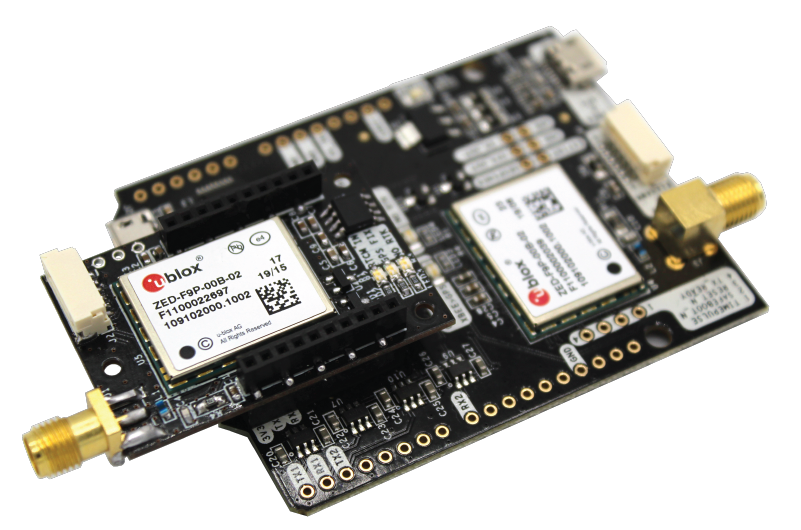
Today I ran the Ardusimple boards standalone and got them passing RTCM corrections and generating a RELPOSNED message (on what they call the “Bottom” board which is the moving rover) and NMEA messages (from what they call the “top” board which is the moving base). The RELPOSNED message matched my physical antenna placement pretty accurately, within a few centimeters. I connected the 2 boards using the headers provided (like in this picture https://www.ardusimple.com/wp-content/uploads/2019/07/simpleRTK2Blite_hookup.png) . I used Ardusimple’s configuration files. I connected my PC to each board simultaneously using two separate serial/USB connections and ran u-center twice - one u-center instance connected to 1 GPS and the other u-center instance connected to the other GPS.
But when I connected these to my Pixhawk (with GPS_AUTO_CONFIG=0) ardurover was not happy…
One thing I noticed is that if GPS_DRV_OPTIONS=1 then Ardurover expects the 2 GPSs to be physically connected using each board’s UART2, which is not how the Ardusimple boards are connected in that “piggyback” mode pictured above. In that mode, the top board’s UART1 is connected to the bottom board and the bottom board’s UART2 is connected to the top board.
Hi Chris,
I suspect that the GPS_DRV_OPTIONS=1 is only really a prompt to the system to configure the attached GNSS modules to use uart2 for RTCM and has no effect on how anything else works. I had a private message from someone recently that has the same setup you describe but also having problems. I am not setup to test any real hardware right now but the current master branch supports RELPOSNED in SITL. I configured the setup you describe with only one F9P connected to the Pixhawk and sending RELPOSNED. GPS_TYPE2 was set to 0. The only reference to the second GNSS module on the Pixhawk are the GPS_POS2 params. With this config in SITL the system was getting and using a moving baseline yaw value from the single GNSS module.
I should be in a position to test this setup tomorrow. What version of the code are you running?
I think that’s right:
It seems you can select either uart 1 or 2 but the current implementation assumes they always must match on base and rover. Maybe we should extend DRV_OPTIONS to allow for the other configurations?
For what it’s worth I have concluded that the Ardusimple boardset ( 2 F9P chips on 2 boards connected piggyback-style) doesn’t work with Ardupilot/Ardurover because the Ardusimple moving base GPS (which is the top board) has UART1 connected to the Pixhawk jst connector and also has UART1 connected to the bottom board (which is the moving rover). Hence Ardusimple expects the moving base to send the RTCM messages to the moving rover on UART1. But, also, Ardurover/Ardupilot expect to receive NMEA messages on that UART1 and also expect to inject RTCM messages (from the other, fixed, base) into that same UART. This configuration doesn’t match any of the Ardupilot/Ardurover automatic GPS configurations.
It seems that one option would be to create GPS_TYPE 19 and 20 for Ardusimple moving base and Ardusimple moving rover, and change the Ardupilot/Ardurover code to configure the GPSs according to how the Ardusimple hardware is built.
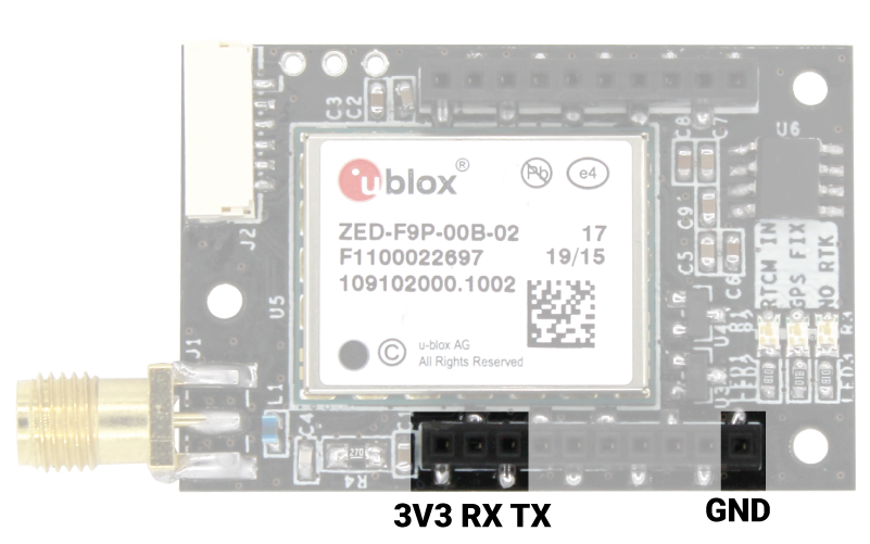
Chris, I would be surprised if this is not possible. Looking at the specs on the Ardusimple website, I believe that there may be an error. The Bottom XBee header states that “This interface is connected to ZED-F9P UART1” which is unusually the same interface as the Pixhawk (JST) connector, however further down the Top XBee header section states that what appears to be the same pins (but on the top side of the board) have: “This interface is connected to ZED-F9P UART2”. If you can confirm that TX/RX pin locations are electrically connected on the top and bottom of the board, I think we will have the answer. I would wager that both sides are connected and that both are connected to UART2. This would make sense as it would allow independant connection of both F9P modules to the Pixhawk and another connection between them.
For the simpleRTK2Blite:
BOTTOM XBee header
You can use this header to connect an to any XBee compatible socket. The following pins are available:
- VCC, which is an input for 3.3V
- XBee UART RX, at 3.3V level
- XBee UART TX, at 3.3V level
- GND
This interface is connected to ZED-F9P UART1.

TOP XBee socket
You can use this socket to connect an XBee compatible radio. The following pins are available:
- VCC, which is a 3.3V output with maximum current 250mA.
- XBee UART RX, at 3.3V level
- XBee UART TX, at 3.3V level
- GND
This interface is connected to ZED-F9P UART2.
@jimovonz thanks for engaging on this.
I checked and the top header and bottom header are not connected through the board. It’s hard to believe, so, video of that test here https://photos.app.goo.gl/J9TuqWoDN7Yi55w39
Note that the top and bottom header TX and RX pins are also “switched”. On the top, the TX is the pin adjacent to 3V3. On the bottom, the RX is the pin adjacent to 3V3.
It occurs to me that I could do a trial connecting the two Ardusimple boards using jumper wires (rather than the “piggyback” style connection using the headers), connecting UART2 from the top board (using the “top XBee socket”) to UART2 on the bottom board (using its headers which are UART2). …
@jimovonz I hooked up my 2 F9P boards so they were connected to each other via UART2. Then each board was connected via UART1 to the Pixhawk4. That didn’t work either. I did observe that they were exchanging RTCM messages as there is an “RTCM In” light that flashes on one of the boards… Would you mind sharing your GPS configuration files?
Hi Chris
I managed to get the system working in default ardusimple configuration.
One thing I think was key was to check the GPA.delta in the logs. Mine was up at 1000 or 1 second.
That was a good clue, so I configured first the rover to send RCTM at 10hz and then the MB to send GPS updates at 10 HZ.
once I had good RTK fix, I got heading straight away and repeatedly.
@graham_new great. Would you mind sending me your gps config files and your ardurover logfile? Just to confirm this is with the 2 GPSs in the “piggyback” configuration?
Hi Chris
I am using this on a copter.
GPS are in piggy back.
I think what solved my issue was to increase the gps rate to 10HZ. First must change it on the LITE baord, then on the classic board.
It is important for both modules to be configured to the same rate. The timing between observations and receiving corrections is critical for MB. It is also for this reason that the communication link between the two units is fast enough. Above 5Hz with the standard setup I see frequent drop outs in the RELPOSNED heading. I have managed a stable 10Hz using the latest firmware, a direct connection for corrections at 921kbps and using only the minimum required msm4 messages. Lately however, I have been experimenting with leaving both F9P modules set up for stand alone rtk and calculating the heading from the positions. This seems to work well and the advantage is that I can now get rtk positrons at up to 40Hz (GPS only, 25Hz with 3 constellations excluding Glonass ). The accuracy of the heading seems to be about half that of a proper MB setup but since we have large vehicles, this is not a problem. I see ~0.5deg total variation using a 1.3m separation (baseline)
@jimovonz thanks for the update. Have you built a custom version of ardurover with code that determines heading based on the two GPS positions?
I have wondered whether I will eventually want another receiver onboard for when one receiver loses rtk fix.
@Christopher_Milner - yes I have customised the code to determine heading based on the relative positions reported by the two on board gnss. I have tested this in SITL, on the bench and briefly on a vehicle. I am hoping to get time tomorrow on a vehicle to more fully test both this and the high precision location code during full autonomous running (Chasing better accuracy).